Ultrasound-Guided Blocks for Chronic Pain Management - Peripheral Structures
Author
Philip Peng, MBBS, FRCPC
Associate Professor
Department of Anesthesia and Pain Management
University Health Network
University of Toronto
Toronto, Ontario
Introduction
Application of ultrasound in pain medicine (USPM) is a rapidly growing field as indicated by the increasing number of USPM workshops held in the past three years in North America, Europe and Asia. Publication of ultrasoundguided interventional pain procedures has also increased at a remarkable rate. A search of the Medline® database revealed only 3 publications of ultrasound-guided or ultrasound-assisted injection techniques (excluding peri-operative and various intra-articular, interlaminar and trigger point injections) between 1982 and 2002 but 42 publications between 2003 and 2008.[1]
Traditional interventional procedures for pain management are often performed by techniques using either landmark or imaging guidance (e.g., fluoroscopy and computed tomography (CT) scan). A comparison of the advantages and disadvantages of various imaging techniques is summarized in Table 1.
Table 1. A Comparison of Fluoroscopy, CT Scan and Ultrasound.
| Fluoroscopy | CT Scan | Ultrasound | |
|---|---|---|---|
| Soft tissue visualization | None to poor | Excellent | Good |
| Radiation risk | + to +++ | ++ | - |
| Cost | +++ to ++++ | +++++ | ++ to +++ |
| Portability | + | - | ++ to +++ |
| Infrastructure | ++ | ++++ | - |
| Real-time guidance | + | - | + |
| Bone imaging | Excellent | Excellent | Poor to good |
| Imaging deep structures | Fairly reliable | Reliable | Unreliable |
In addition, the application of ultrasound in pain medicine can be divided into three distinct areas: peripheral, axial and musculoskeletal structures (Table 2). As demonstrated in these two tables, ultrasound is an affordable and easily available technology without radiation hazard. It reliably provides visualization of soft tissues that are important in the performance of pain blocks for peripheral structures. Furthermore, ultrasound allows real-time visual guidance during needle advancement and visualization of injectate around the target structure.
Table 2. A Comparison of Ultrasound Imaging for Peripheral, Axial and Musculoskeletal Structures in Pain Medicine.
| *The assigned level of difficulty is determined by the founding members of the ASRA Ultrasound for Pain Medicine Special Interest Group in 2009. The level of difficulty is appraised based on 4 criteria (Table 2b). The summation scores from these 4 criteria are: 4 to 6 for Level I (Basic); 7 to 9 for Level II (Intermediate); and 10-12 for Level III (Advanced). Adapted with permission from USRA (www.usra.ca). | |||
| Ultrasound | Peripheral | Axial | Musculoskeletal |
| Target structures visualization | Soft Tissue (++) | Spine (Poor to +) | Bursa/joint (+ to ++) |
| Level of difficulty* | I–II | II–III | I |
| Conventional technique | Mostly blind | Image-guided | Mostly blind |
Table 2b. Scoring System for the Level of Difficulty for Ultrasound-Guided Interventional Pain Procedures.
| For each block the total score based on the following 4 criteria | |
|---|---|
| Ease of visualization of target structure | 1: easy, 2: intermediate, 3: difficult |
| Ease of identifying structures | 1: easy, 2: intermediate, 3: difficult |
| Technical performance of block | 1: easy, 2: intermediate, 3: difficult |
| Risk of complication to adjacent structures | 1: low, 2: intermediate, 3: high |
The objective of this review is to describe and summarize the anatomy, sonoanatomy and feasibility data published in the literature on four selected USPM procedures:
- stellate ganglion block;
- suprascapular block;
- ilioinguinal/iliohypogastric nerve block and
- piriformis muscle injection.
For a detailed review of all the USPM blocks for peripheral, axial and musculoskeletal structures, please visit the USPM Special Interest Group section of the ASRA website.
Stellate Ganglion Block
Stellate ganglion block (SGB) is commonly performed in patients with sympathetic maintained pain, vascular insufficiency and for a variety of pain conditions.[2] The most widely practiced approach to SGB is the paratracheal approach, in which the needle is inserted towards the prominent anterior tubercle of the cervical sixth vertebra (Chassaignac tubercle). However, it is important to note that the middle cervical ganglion is located at the C6 level while the stellate ganglion is located opposite to the neck of first rib (Figure 1).[1]
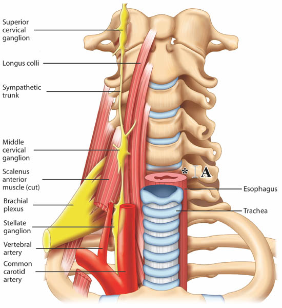
Figure 1. Prevertebral region of the neck. The target site for needle insertion in classical approach is marked as *. The breadth of the transverse process is marked as A. Reproduced with permission from USRA (usra.ca).
Ultrasound Guided Stellate Ganglion Block
Anatomy and Sonoanatomy
The sympathetic fibers innervating the head, neck, and upper limbs arise from the first few thoracic segments. They ascend through the sympathetic chains, and synapse in the superior, middle and inferior cervical ganglia. The stellate ganglion, formed by fusion of the inferior cervical and first thoracic ganglion, is located adjacent to the neck of the first rib, lateral to the longus colli muscle and posterior to the vertebral artery (Figure 1). The postganglionic fibers are sent from the stellate ganglion to the cervical nerves (seventh and eighth) and first thoracic nerve to provide sympathetic innervation to the upper limbs.[3-4] The preganglionic fibers of the head and neck region continue to travel cephalad to the superior and middle cervical ganglion through the cervical sympathetic trunk, which is located between the carotid sheath and the prevertebral fascia.[5-6]
The key structures to be identified for ultrasound-guided SGB injection are: vessels within the carotid sheath, prevertebral fascia, longus colli muscle, anterior tubercle of the sixth cervical vertebra and the thyroid (Figure 2a).
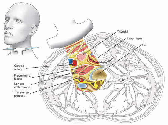
Figure 2 a. Cross section of the neck at the sixth cervical vertebral level correlating with the ultrasonographic image. Reproduced with permission from USRA (www.usra.ca).
When performing the classical approach, the needle is inserted in the vicinity of the cervical sympathetic trunk, which runs anterior and lateral to the cervical vertebral bodies in a space covered by the posterior fascia of the carotid sheath anteriorly and by the prevertebral and alar fascia posteriorly.[7] The target for injection is therefore the prevertebral fascia.[1] This fascia lies over the vertebral bodies, the transverse processes, the longus colli, capitis, and anterior scalene muscles. Ultrasound allows direct visualization of vessels and soft tissues (thyroid, esophagus, and muscles) in the cervical region and potentially minimizes the risk of needle trauma to these structures (Figure 2b, c).[1]
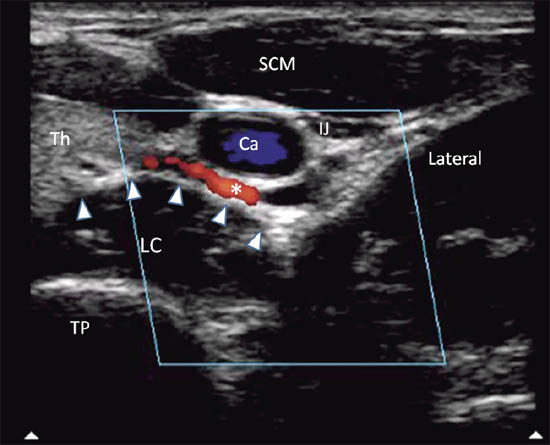
Figure 2 b. Ultrasonographic image with color Doppler. The inferior thyroidal artery was indicated with *; the prevertebral fascia is marked by solid arrowhead. Ca = carotid artery; IJ = internal jugular vein; SCM = sternocleidomastoid muscle; Th = thyroid; LC = longus colli muscle; TP = transverse process. Reproduced with permission from USRA (www.usra.ca).
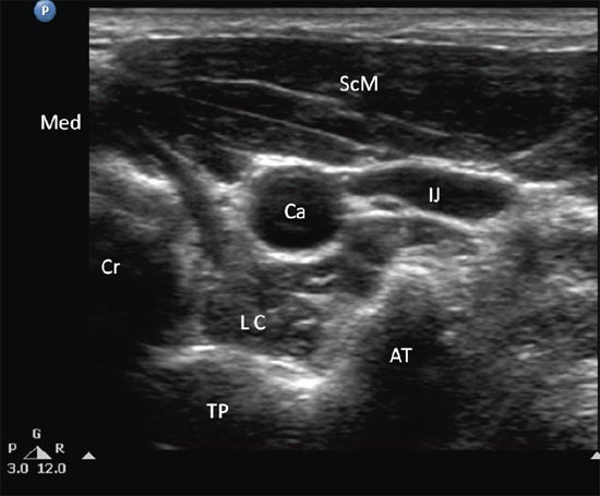
Figure 2 c. Ultrasonographic image of neck at C6. Ca = carotid artery; IJ = internal jugular vein; SCM = sternocleidomastoid muscle; LC = longus colli muscle; TP = transverse process; AT = anterior tubercle; Cr = cricoid; Med = medial. Reproduced with permission from USRA (www.usra.ca).
Advantages of the Ultrasound Guided Technique
The conventional SGB techniques are landmark-based and fluoroscopyguided. However, ultrasound offers a number of advantages over the conventional approaches especially those that are performed “blind”. They are:
1. Identification of the Osteology of C6 Vertebra
Detailed measurement of C6 vertebra shows that the minimal breadth (cephalo-caudal distance) of the Chassaignac tubercle is 6 mm (Figure 1).[8] Thus, it can be easily missed with needle advancement with conventional technique. Consequently, it is possible to puncture the vertebral artery or the nerve root, which is usually protected by the anterior tubercle of the C6. The target for ultrasound-guided technique is the prevertebral fascia (see below) and ultrasound allows real-time imaging guidance during needle advancement so that needle entry into the target soft tissue is visualized.
2. Identification of the Vertebral Artery
The target for landmark based SGB is needle contact with the anterior tubercle of the C6 transverse process. It is generally believed that ‘once the needle is in contact with the bone, it is safe’. The vertebral artery usually ascends between the scalenus anterior and longus colli muscles, and passes in front of the C7 vertebra before entering the foramen in the transverse process of C6 and above. However, this may only apply to 90% of the patients. The vertebral artery may enter the foramen of the transverse process of C4 or C5 in 10% of patients.[9] Although contrast injection in fluoroscopy-guided technique helps to avoid inadvertent injection of local anesthetic into this artery, needle misplacement is recognized only after the artery has been punctured. A modified fluoroscopy-guided oblique approach may minimize the risk of vertebral artery puncture as the needle is directed to the junction of the uncinate process and the vertebral body.[10]
3. Identification of the Esophagus
Esophagus, or hypopharynx, is not completely covered by the cricoid cartilage (Figure 2d). Not infrequently, the esophagus is exposed beyond the midline vertebral body lying anterior to the medial part of the transverse process. The esophagus can be within the needle path to the cervical sympathetic trunk.
A magnetic resonance imaging (MRI) observational study showed that esophagus was deviated to one side behind the cricoids in 52% of the patients. It is noted that 40–60% of the esophagus is exposed in 5% of the individuals examined and 20–40% of the esophagus is exposed in another 26% of individuals.[11] Mediastinitis may result if the block needle punctures an unrecognized diverticulum.[12] Moreover, unintentional injection and blockade of the external laryngeal branch of the superior laryngeal nerve or recurrent laryngeal nerve will cause voice hoarseness. Esophageal needle puncture may also cause the sensation of a ‘foreign body’ in the throat after the procedure.
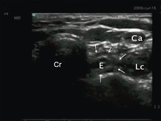
Figure 2 d. Ultrasonographic image at the same level showing the deviation of esophagus (outlined by line arrows). Ca = carotid artery; LC = longus colli muscle; E = esophagus; Cr = cricoid. Reproduced with permission from USRA (www.usra.ca).
4. Lowering the Risk of a Retropharyngeal Hematoma
Cervical arteries, especially the inferior thyroidal artery, often pass in front of the needle path and the prevertebral fascia (Figure 2b). Hematoma developed following accidental vascular puncture was a commonly encountered complication (25%) in the first case series comparing ultrasound-guided with ‘blind’ injection technique.[13] A large retropharyngeal hematoma following stellate ganglion block can be life-threatening.[14]
5. Differentiation of Suprafascial and Subfascial Injection
Fluoroscopy does not visualize the soft tissues or vascular structures described above. It relies on the C6 transverse process as the surrogate landmark for needle contact and local anesthetic injection. As discussed above, the cervical sympathetic chain lies in the fascial plane between the carotid sheath and the prevertebral fascia. Local anesthetic injection following ‘bone contact and needle withdrawal’ has been shown to spread anterior to the prevertebral fascia and in the paratracheal space in most patients without significant caudal spread.
It has been suggested that subfascial injection may result in a more caudal spread, a higher rate of successful sympathetic blockade of the upper limb and a lower risk of hoarseness.[7][15] Although not proven in randomized trials, subfascial injection has the theoretical advantage of promoting local anesthetic spread more caudally to contact the cervical sympathetic chain and less anteriorly and laterally into the paratracheal space.
Technical Considerations
The patient is placed in the supine position with the neck in slight extension. A high frequency linear transducer (6–13 MHz) is placed at the level of C6 to allow cross-sectional visualization of anatomic structures, including the transverse process and anterior tubercle of C6, longus colli muscle and prevertebral fascia, carotid artery and thyroid gland (Figure 2b, c). A prescan is important in planning the path of needle insertion as the presence of the esophagus and the inferior thyroidal artery1 may obviate the needle insertion path between the carotid artery and trachea. In that situation, the needle may be inserted lateral to the carotid artery, which is the author’s preferred route.
The tip of the needle is directed under the prevertebral fascia superficial to the longus colli (Figure 2e). A total of 5mL of local anesthetic is injected. Visualization of the spread of injectate under real-time scanning is important as the absence of this may suggest unsuspected intravascular injection.
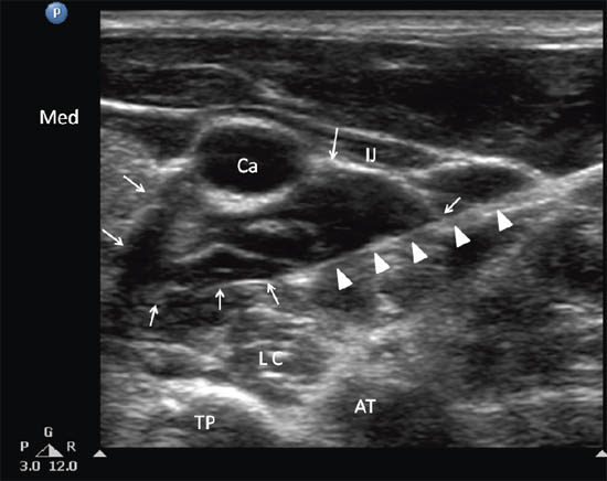
Figure 2 e. Ultrasonographic image of neck at C6 as in Figure 2 c following injection of local anesthetic. The needle was indicated by solid arrows and the local anesthetic was outlined by the line arrows. Ca = carotid artery; IJ = internal jugular vein; LC = longus colli muscle; TP = transverse process; AT = anterior tubercle; Med = medial. Reproduced with permission from USRA (www.usra.ca).
Suprascapular Nerve Block
Suprascapular nerve (SSN) block is indicated for treatment of acute shoulder pain that follows trauma or shoulder surgery and a variety of chronic shoulder pain syndromes. It is also indicated as a diagnostic block for diagnosis of suprascapular neuropathy.[1]
Ultrasound Guided Suprascapular Nerve Block
Anatomy and Sonoanatomy
The SSN originates from the superior trunk of the brachial plexus (formed by the union of the fifth and sixth cervical nerves), and courses under the trapezius before it passes under the transverse scapular ligament in the suprascapular notch (Figure 3). It then passes beneath the supraspinatus muscle, and curves around the lateral border of the spine of the scapula (spinoglenoid notch) to the infraspinatous fossa (Figure 6). In the supraspinatous fossa it gives off two branches, one to the supraspinatus muscle and another as an articular branch to the shoulder joint. In the infraspinatous fossa it gives off branches to the infraspinatous muscle, and to the shoulder joint and scapula. The sensory component of the SSN provides fibers to about 70% of the shoulder joint
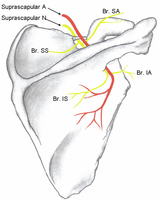
Figure 3. Suprascapular nerve and its branches. The superior articular branch (Br. SA) supplies the coracohumeral ligament, subacromial bursa and posterior aspect of the acromioclavicular joint capsule; the inferior articular branch (Br. IA) supplies the posterior joint capsule. Br. SS = branch to the supraspinatus muscle; Br. IS = branch to the infraspinatus muscle. Reproduced with permission form USRA (www.usra.ca).
The ‘U’ or ‘V’ shaped suprascapular notch is located on the superior margin of the scapula, medial to the coracoid process (Figure 4). However, the notch is absent in up to 8% of cadavers.[16] Above the notch run the suprascapular artery and vein; however, the artery may travel through the notch along with the suprascapular nerve in a small number of individuals. The supraspinous fossa is bordered by the spine of the scapula dorsally, the plate of the scapula ventrally and by the supraspinatus fascia superiorly.
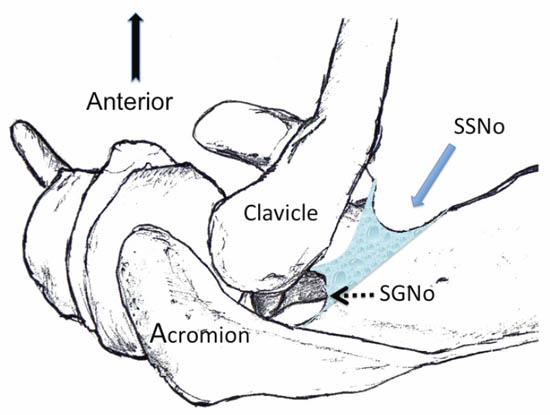
Figure 4. Superior view of the left shoulder. The suprascapular nerve enters the suprascapular fossa through the suprascapular notch (SSNo) and then exits through the spinoglenoid notch (SGNo) into the infrascapular fossa. Reproduced with permission from USRA (www.usra.ca).
When imaging the suprascapular fossa with the ultrasound, two key muscles to be identified in the scan are the trapezius and supraspinatus muscles (Figure 5). The SSN is often seen accompanied by the suprascapular artery on the floor of the scapular spine between the suprascapular notch and spinoglenoid notch (Figure 4 and 6).
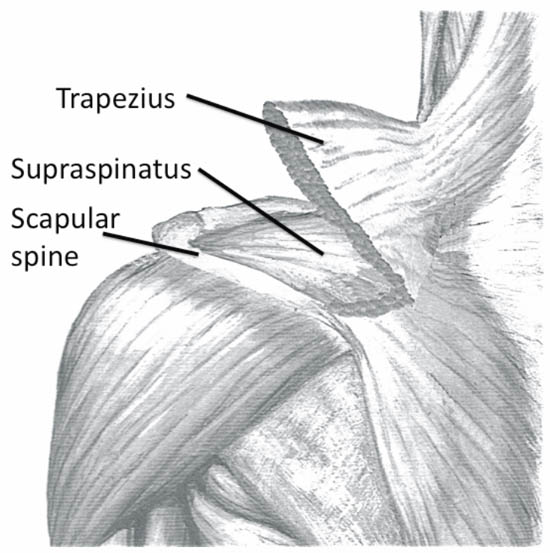
Figure 5. Left shoulder showing muscle layers of the suprascapular fossa. Reproduced with permission from USRA (www.usra.ca).
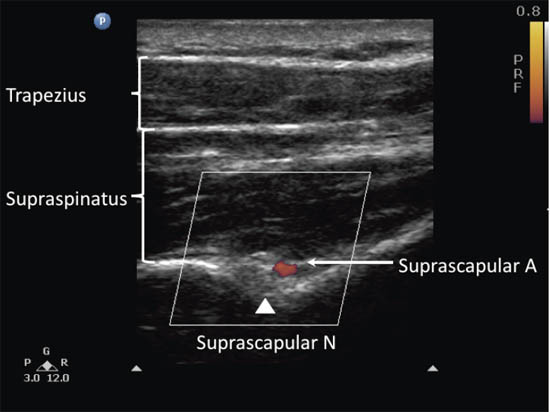
Figure 6. Ultrasonographic image of the suprascapular nerve on the floor of the scapular spine between the suprascapular notch and the spinoglenoid notch. Both suprascapular nerve and artery run underneath the fascia of the supraspinatus muscle. Reproduced with permission from USRA (www.usra.ca).
Advantages of the Ultrasound Guided Technique
The ideal site to perform the SSN injection is at the floor of the scapular spine between the suprascapular notch and spinoglenoid notch (Figure 4).[17] This technique does not rely on the notch as a needle target. This virtually avoids the risk of pneumothorax because the needle is directed away from the thorax. This technique is therefore feasible in individuals without a suprascapular notch (8% of the population). Second, the suprascapular fossa forms a compartment which limits the spread of local anesthetic predominantly around the nerve, allowing a small volume to achieve a perinerual injection.[18] In contrast, local anesthetic injection at the suprascapular notch level may result in spread to the brachial plexus resulting in an unintentional brachial plexus blockade.[18]
Technical Considerations
The patient can be sitting or prone. The scapula spine, coracoid process and acromion are useful landmarks to be identified. Ultrasound scanning is performed with a linear high frequency probe (7-13 MHz) that is placed in a coronal plane over the suprascapular fossa with a slight anterior tilt. The probe is placed in an orientation such that it is in the short axis to the line joining the coracoid process and the lateral border of the acromion which approximates the position of the spinoglenoiod notch.[1] The supraspinatus and trapezius muscles and the bony fossa underneath should come into view (Figure 6). By angling the ultrasound probe in a cephalo-caudad direction, the suprascapular nerve and artery should be brought into view in the trough of the floor of the fossa. The nerve, approximately 25 mm in diameter, can be difficult to visualize.
A 22-gauge, 80-mm needle is inserted along the longitudinal axis of the ultrasound beam. The needle is inserted in-plane from the medial aspect of the probe to avoid contact with the acromion process on the lateral side. Because of the proximity of the nerve, an injectate volume of 5-8 mL is usually sufficient.
Ilioinguinal and Iliohypogastric Nerve
The ilioinguinal (II), iliohypogastric (IH) and genitofemoral (GF) nerves are called the “border nerves” because they provide sensory innervation to the area between the thigh and abdomen.1 Because of their location and variable course, these nerves are susceptible to injury in surgical procedures involving the lower abdomen. Open appendectomy, inguinal herniorraphy, low transverse incisions (e.g. Pfannenstiel incision) and trocar insertion for laparoscopic surgery of the abdomen and pelvis may injure these nerves.[19-20] Nerve injury can cause groin pain that radiates to the scrotum or testicle in males, the labia majora in women, and the medial aspect of the thigh.[21] Chronic pain after inguinal repair is reported to be as high as 54% with one third of these patients reporting moderate to unbearable pain.[22] Blockade of these nerves help to diagnose and/or treat pain in these patients.[1][21][23]
Ultrasound Guided Ilioinguinal and Iliohypogastric Nerve Block
Anatomy and Sonoanatomy
The ilioinguinal and iliohypogastric nerves originate from the T12 and L1 nerve roots.[24-25] They emerge near the lateral border of the psoas major muscle and descend diagonally towards the iliac crest (Figure 7). The iliohypogastric nerve pierces the transversus abdominis muscle above the iliac crest, midway between the iliac crest and the twelfth rib. The ilioinguinal nerve runs caudally and parallel to the iliohypogastric nerve.
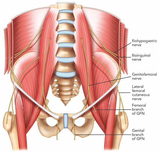
Figure 7. The course of the ilioinguinal, iliohypogastric and genitofemoral nerve. GFN = genitofemoral nerve. Reproduced with permission from USRA (www.usra.ca).
Above and lateral to the anterior superior iliac spine (ASIS), both nerves can be found consistently (90%) between the transversus abdominis and internal oblique muscles.[26] Terminal branches of the iliohypogastric nerve perforate the external oblique muscle aponeurosis 4 cm lateral to the midline to supply the skin over the lower portion of the rectus abdominis muscle.[25] The iliohypogastric nerve also provides sensory innervation to the skin above the tensor fasciae lata through a lateral cutaneous branch.[25] Terminal branches of the ilioinguinal nerve enter the inguinal canal through the deep inguinal ring. It may lie upon the cremasteric muscle and fascial layer of the spermatic cord in men or round ligament in women.[27-28] It is often accompanied by the genital branch of the genitofemoral nerve and wide variations in the course of these nerves within the inguinal canal have been documented.1 The terminal sensory branches of the ilioinguinal nerve may innervate the skin of the mons pubis, inner thigh, inguinal crease, and anterior surface of the scrotum or anterior one-third of the labia.
Lateral and above the ASIS, three layers of muscle—the external oblique (EO), internal oblique (IO) and transversus abdominis (TA) muscles are visualized. The ilioinguinal nerve can be found in the fascial plane between the internal oblique and transverse abdominis muscles close to the iliac crest (< 1.5 cm). Iliohypogastric nerve is found medial to the ilioinguinal nerve or the two nerves may then merged together. The deep circumflex iliac artery can be found in this fascial plane.
Advantages of the Ultrasound Guided Technique
Imaging and cadaver studies show that there is a high degree of anatomic variability in the course and branching pattern of the ilioinguinal and iliohypogastric nerves, and the site of penetration from the fascial layers and dominance patterns.1 The II and IH nerve anatomy described above may only be consistent in 41.8% of patients.[29] Furthermore, the sites at which the II and IH nerves pierce the abdominal wall muscle layers are significantly variable.[20] Unfortunately, virtually all landmark based injection techniques recommend injection medial to the ASIS.[1] With ultrasound imaging, it is now clear that the II and IH nerves are most consistently visualized lateral and superior to the ASIS where the nerves are found between the transverses abdominis and internal oblique muscular layers (90%).[25-26] Ultrasound is an excellent imaging tool to visualize the abdominal muscle layers and ultrasound-guided nerve block has been validated in a cadaver study with 95% accuracy in localizing both nerves.[30]
Technical Considerations
When performing II and IH nerve blockade under ultrasound guidance, it is important to first identify the abdominal wall muscle layers: EO, IO and TA. The patient is placed in the supine position. Both nerves are relatively superficial, thus a high frequency (6–13 MHz) linear probe will provide optimal visualization. Initial scanning lateral and superior to the ASIS is recommended. The probe placed with the lateral edge on top of the iliac crest aims to capture a transverse (short axis) view of the II and IH nerves (often runs parallel to the inguinal ligament).
At this location the iliac crest has a hyperechoic outline with a hypoechoic bony shadow below. The three muscular layers of the abdominal wall are seen lateral to the iliac crest (Figure 8). Below the TA, peristaltic bowel movement can be detected. It may be necessary to tilt the probe caudad or cephalad to optimize the image. Once the muscular layers are identified, the II and IH nerves will be found in the fascial plane between the IO and TA muscle layers. Both nerves should be within 1.5 cm from the iliac crest at this site, with the II nerve closer to the iliac crest. In some cases, the nerves may run approximately 1 cm apart.[1] The deep circumflex iliac artery which is close to the two nerves in the same fascial layer is detected with colour Doppler (Figure 9).
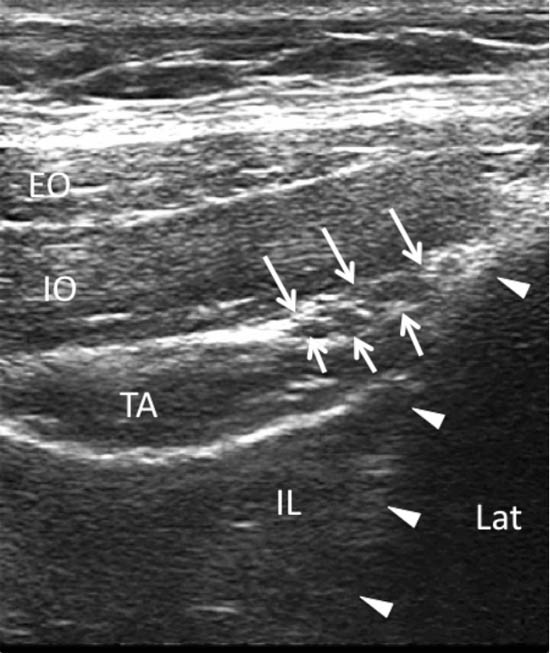
Figure 8. A sonogram showing three layers of abdominal muscles and the ilioinguinal and iliohypogastric nerves within the fascial plane between IO and TA. Arrows = ilioinguinal and iliohypogastric nerves; arrowheads = outline of the iliac crest; EO = external oblique muscle; IO = internal oblique muscle; TA = transversus abdominis muscle; IL = iliacus muscle; LAT = lateral. Reproduced with permission from USRA (www.usra.ca).
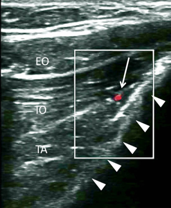
Figure 9. Color Doppler showing the deep circumflex iliac artery (arrow pointing at the red dot). Arrowheads = outline of the iliac crest. EO = external oblique muscle; IO = internal oblique muscle; TA = transversus abdominis muscle. Reproduced with permission from USRA (www.usra.ca).
Once satisfied with nerve visualization, a 22-guage spinal needle is advanced towards the nerves under real time guidance. Either an out-of-plane or in-plane technique may be used although this author favors the in-plane technique. The needle is advanced until the needle tip enters the fascial plane between the IO and TA muscles and adjacent to the II and IH nerves (Figure 10). At this point, needle tip position and proper fluid spread can be confirmed by hydrodissection with normal saline. When it is difficult to visualize the nerves, local anesthetic injection in the fascial plane between the TA and IO muscles to ensure adequate medial and lateral spread is recommended. Injection of 6-8 mL of local anesthetic (bupivacaine 0.5%) and steroid (depo-medrol 40 mg) to surround both nerves is the desired result.
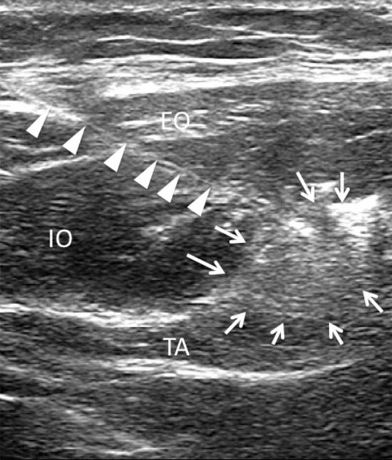
Figure 10. A sonogram showing a needle (arrowheads) inserted with the inplane technique and the spread of local anesthetic and steroid (arrows). EO = external oblique muscle; IO = internal oblique muscle; TA = transversus abdominis muscle. Reproduced with permission from USRA (www.usra.ca).
Piriformis Muscle Injection
Piriformis syndrome is an uncommon cause of pain in the buttock or hip radiating down the posterior aspect of the leg. The etiology may arise from piriformis muscle hypertrophy, inflammation, or anatomical variations, all of which can either compress or irritate the sciatic nerve.[31]
Injection techniques to manage this syndrome include injection of steroid and local anesthetic around or into the substance of the muscle.[32] Evidence supports the injection of botulinum toxin into the muscle in conjunction with physiotherapy to relieve pain.[33]
Ultrasound Guided Piriformis Muscle Injection
Anatomy and Sonoanatomy
The piriformis muscle originates from the ventral surface of the S2 to S4 vertebrae as fleshy digitations, and runs laterally and anterior to the sacroiliac joint before exiting the pelvis through the greater sciatic foramen (Figure 11).[31] It then inserts into the upper border of the greater trochanter as a round tendon. The piriformis muscle functions as an external rotator of the lower limb in the erect position, an abductor when supine, and a weak hip flexor when walking
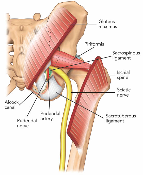
Figure 11. Posterior view of the pelvis showing the piriformis muscle. The gluteus maximus muscle was removed to show the deeper structures. Note that the pudendal nerve, pudendal artery and sciatic nerve run caudal to the piriformis muscle. Reproduced with permission from USRA (www.usra.ca).
All neurovascular structures exiting the pelvis to the buttock pass through the greater sciatic foramen.[34] Inferior to the piriformis lies the inferior gluteal artery and nerve, the internal pudendal artery, the pudendal nerve, nerve to obturator internus muscle, posterior femoral cutaneous nerve, nerve to quadratus lumborum muscle and the sciatic nerve. The anatomical relationship between the piriformis muscle and sciatic nerve is variable. Most commonly (78%–84%), the sciatic nerve passes below the piriformis muscle.[35-36] Less frequently (12%–21%), the nerve is divided, passing through and below the muscle.[36] Other less common variations are a divided nerve passing through and above the piriformis, a divided nerve passing above and below the muscle, an undivided nerve passing above piriformis and an undivided nerve passing through the muscle. The close relationship of the piriformis muscle to the sciatic nerve explains why patients experiencing piriformis syndrome may also experience symptoms of sciatic nerve irritation.
Advantages of Ultrasound Guided Techniques
The target for injection is either the muscle itself or just outside the muscle. Ultrasound offers direct visualization of the gluteal muscle layers, real-time guidance for needle advancement and confirmation of proper local anesthetic spread. Accuracy of ultrasound guided needle placement has been shown to approach 95% in a recent cadaveric study.[37] Adjacent anatomical structures such as the sciatic nerve are also visualized. The success rate is comparable to that achieved with CT scan or MRI (100%).[38-39] However, ultrasound technology is less costly and more likely to be available to physicians than CT and MRI scans.
Other techniques e.g., nerve stimulator and EMG technique are also utilized for piriformis muscle injection but these techniques again fail to visualize the needle, the muscle or the sciatic nerve.[1] Electrophysiological test has its intrinsic limitation. A previous study demonstrated a relatively low sensitivity when nerve was localized through electrical stimulation using a paresthesia or a motor response (38.2% and 74.5%, respectively).[40] Muscle stimulation cannot confirm if the needle is in contact with the muscle surface or within it.
The success rate of injection inside or around the piriformis muscle is greater when an imaging modality is used. Fluoroscopic-guided piriformis muscle injections depend on the presence of a characteristic intrapiriformis contrast spread pattern to confirm correct needle placement (Figure 12).[41] However, a cadaver study showed that fluoroscopically-guided contrast-controlled injection was only accurate in 30% of the intended intrapiriformis injections.[37] In cases where the needle was incorrectly placed, the needle was usually within the gluteus maximus muscle, which overlies piriformis.
Figure 12. A picture showing radiographic contrast outlining the piriformis muscle (arrows). Reproduced with permission from USRA (www.usra.ca).
Technical Considerations
The patient is placed in a prone position. A low frequency (2–5 MHz) curvilinear probe is required to visualize the muscle given its location deep to the gluteus maximus muscle. The ultrasound probe should be first placed transversely over the posterior superior iliac spine (PSIS) to visualize the sacroiliac joint. Once this is seen, the transducer is moved laterally to view the ilium. The posterior aspect of the iliac wing should be clearly visualized as a hyperechoic line extending laterally (Figures 13 a and 13 b).
Once the iliac wing is identified, the angle of the probe is rotated such that it would be in line with the long axis of the piriformis muscle as it runs from the sacrum to the greater trochanter. As scanning continues caudally, the hyperechoic line of the ilium starts to recede from the medial aspect of the image at the level of the sciatic notch. The lateral aspect of the ultrasound image continues to display a curved hyperechoic line representing the ischium. At this level, two separate muscular layers are identified: the gluteus maximus and the piriformis muscles (Figure 13 c). When internally and externally rotate the patient’s hip with the knee flexed, the piriformis muscle can be seen gliding underneath the gluteus maximus muscle.
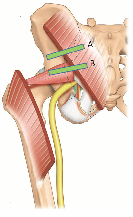
Figure 13 a. Two possible positions of the ultrasound probe for scanning the the piriformis muscle and the pudendal nerve. Reproduced with permission from USRA (www.usra.ca).
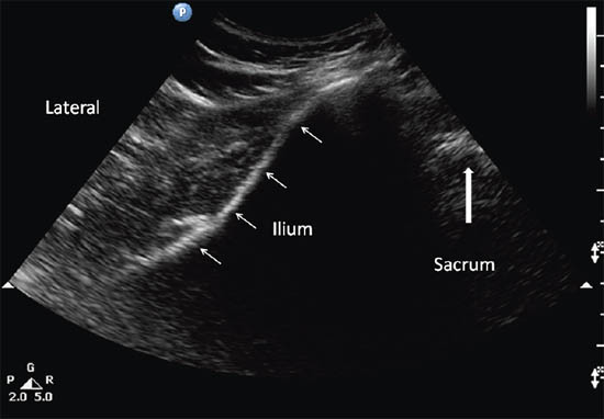
Figure 13 b. Sonogram showing the underlying structures when the probe is at position A. Reproduced with permission from USRA (www.usra.ca)
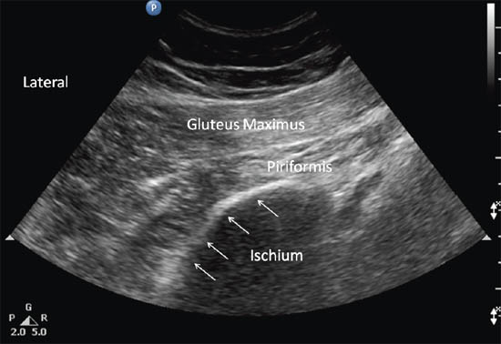
Figure 13 c. Sonogram showing the piriformis muscle and surrounding structures (gluteus maximus muscle and ischium) when the probe is at position B. Reproduced with permission from USRA (www.usra.ca).
Due to the depth of the muscle, a 22 gauge 120 mm nerve stimulating needle is used. The author recommends concomitant use of a nerve stimulator to avoid unintentional injection of the sciatic nerve which is known to travel in variable courses in this region. In addition, the nerve stimulator can confirm proper needle tip position inside the piriformis muscle when piriformis muscle twitching is observed on the monitor.
Needle insertion using an in-plane technique from the medial aspect of the probe is recommended. The needle is inserted laterally into the muscle belly of the piriformis in the sciatic notch. If intramuscular injection is the goal, the needle should be slowly advanced until strong piriformis muscle contraction is evident on the monitor. A small volume of normal saline (0.5 mL) may be injected to confirm needle position within the muscle. Once satisfied with needle position, a small volume (1 to 2 mL) of medication (either a mixture of 1 mL of 0.5% bupivacaine and 40 mg Depo-medrol or 50 units of Botulinum toxin A diluted in 1 mL of normal saline) may be injected into the muscle.
Conclusion
Ultrasound is a valuable tool for imaging peripheral structures, guiding needle advancement and confirming the spread of injectate around the target structure, all without exposing healthcare providers and patients to the risk of radiation. Most of the ultrasound-guided interventional procedures for peripheral structures have been validated and thus allow accurate performance of these procedures.
References
- Peng P, Narouze S. Ultrasound-guided interventional procedures in pain Medicine: A review of anatomy, sonoanaotmy and procedures. Part I: Nonaxial structures. Reg Anesth Pain Med 2009; 34:458-474
- Elias M. Cervical sympathetic and stellate ganglion blocks. Pain Physician 2000; 3:294-304
- Williams PL. 1995. Gray’s Anatomy. 38th Ed. New York: Churchill Livingstone
- Hogan QH, Erickson SJ. MR Imaging of the stellate ganglion: normal appearance. Am J Roentgen 1992; 158:655-9
- Kiray A, Arman C, Naderi S, Güvencer M, Korman E. Surgical anatomy of the cervical sympathetic trunk. Clin Anat 2005;18:179-185.
- Civelek E, Kiris T, Hepgul K, Canbolat A, Ersoy G, Cansever T. Anterolateral approach to the cervical spine: major anatomical structures and landmarks. J Neurosurg Spine 2007; 7:669-678
- Christie JM, Martinez CR. Computerized axial tomography to define the distribution of solution after stellate ganglion nerve block. J Clin Anesth. 1995; 7:306–311
- Janik JE, Hoeft MA, Ajar AH, Alsofrom GF, Borrello MT, Rathmell JP. Variable osteology of the sixth cervical vertebra in relation to stellate ganglion block. Reg Anesth Pain Med 2008; 33:102-108
- Matula C, Trattnig S, Tschabitscher M, Day JD, Koos WT. The course of the prevertebral segment of the vertebral artery: Anatomy and clinical significance. Surg Neurol 1997; 48:125-131
- Abdi S. A new and easy technique to block the stellate ganglion. Pain Physician. 2004; 7:327-331
- Smith KJ, Dobranowski J, Yip G, Dauphin A, Choi PT. Cricoid pressure displaces the esophagus: An observational study using magnetic resonance imaging. Anesthesiology 2003; 99:60-4
- Narouze S, Vydyanathan A, Patel N. Ultrasound-guided stellate ganglion block successfully prevented esophageal puncture. Pain Physician 2007; 10:747–752.
- Kapral S, Krafft P, Gosch M, Fleischmann D, Weinstabl C. Ultrasound imaging for stellate ganglion block: Direct visualization of puncture site and local anesthetic spread. Reg Anesth 1995; 20:323-328
- Higa K, Hirata K, Hirota K, Nitahara K, Shono S. Retropharyngeal hematoma after stellate ganglion block. Anesthesiology 2006; 105:1238-1245.
- Shibata Y, Fujiwara Y, Komatsu T. A new approach of ultrasound-guided stellate ganglion block. Anesth Analg 2007; 105:550-551
- Natsis K, Totlis T, Tsikaras P, Appell HJ, Skandalakis P, Koebke J. Proposal for classification of the suprascapular notch: a study on 423 dried scapulas. Clin Anat 2007;20:135-139.
- Peng P, Wiley MJ, Liang J, Bellingham G. Ultrasound-guided suprascapular nerve block: A correlation with fluoroscopic and cadaveric findings. Can J Anesth 2010; 57: 143-148
- Feigl GC, Anderhuber F, Dorn C, Pipam W, Rosmarin W, Likar R. Modified lateral block of the suprascapular nerve: a safe approach and how much to inject? A morphological study. Reg Anesth Pain Med 2007;32:488-494.
- Luijendijk RW, Jekel J, Storm RK, et al. The low transverse Pfannenstiel incision and the prevalence of incisional hernia and nerve entrapment. Ann Surg 1997;225:365-369.
- Whiteside JL, Barber MD, Walters MD, Falcone T. Anatomy of the ilioinguinal and iliohypogastric nerves in relation to trocar placement and low transverse inscisions. Am J Obst Gynecol 2003;189:1574-1578.
- Peng PWH, Tumber PS. Ultrasound-guided interventional procedures for patients with chronic pelvic pain-a description of techniques and review of the literature. Pain Physician 2008;11:215-224.
- Poobalan AS, Bruce J, Smith EC, King PM, Krukowski ZH, Chambers WA. A review of chronic pain after inguinal herniorrhaphy. Clin J Pain 2003;19:48-54.
- Bellingham GA, Peng PWH. Ultrasound-guided interventional procedures for chronic pelvic pain. Tech Reg Anesth Pain Manag. 2009;13:171-178.
- Rab M, Ebmer And J, Dellon AL. Anatomic variability of the ilioinguinal and genitofemoral nerve: Implications for the treatment of groin pain. Plast Reconstr Surg 2001; 108: 1618-23.
- Mandelkow H, Loeweneck H. The iliohypogastric and ilioinguinal nerves. Distribution in the abdominal wall, danger areas in surgical incisions in the inguinal and pubic regions and reflected visceral pain in their dermatomes. Surg Radiol Anat 1988; 10: 145-9
- Jamieson RW, Swigart LL, Anson BJ: Points of parietal perforation of the ilioinguinal and iliohypogastric nerves in relation to optimal sites for local anaesthesia. Q Bull Northwest Univ Med Sch 1952; 26: 22-6
- Oelrich TM, Moosman DA: The aberrant course of the cutaneous component of the ilioinguinal nerve. Anat Rec 1977; 189: 233-6
- Ducic I, Dellon AL. Testicular pain after inguinal hernia repair: An approach to resection of the genital branch of genitofemoral nerve. J Am Coll Surg 2004; 198: 181-4
- al-Dabbagh, AK. Anatomical variations of the inguinal nerve and risks of injury in 110 hernia repairs. Surg Radiol Anat 2002;24:102-107.
- Eichenberger U, Greher M, Kirchmair L, Curatolo M, Morigg B. Ultrasound-guided blocks of the ilioinguinal and iliohypogastric nerve: Accuracy of a selective new technique confirmed by anatomical dissection. Br J Anaesth 2006;9:238-243.
- Benzon HT, Katz JA, Benzon HA, et al.: Piriformis syndrome: Anatomic considerations, a new injection technique, and a review of the literature. Anesthesiology 98: 1442-8, 2003
- Hanania M, Kitain E: Perisciatic injection of steroid for the treatment of sciatica due to piriformis syndrome. Reg Anesth Pain Med 1998; 23: 223-8
- Fishman LM, Anderson C, Rosner B: Botox and physical therapy in the treatment of piriformis syndrome. Am J Phys Med Rehabil 2002;81: 936-42
- Papadopoulos EC, Khan SN. Piriformis syndrome and low back pain: a new classification and review of the literature. Orthop Clin N Am 2004;35:65-71.
- Pecina M. Contribution to the etiological explanation of the piriformis syndrome. Acta Anat. 1979;105:181-187.
- Beason LE, Anson BJ. The relation of the sciatic nerve and its subdivisions to the piriformis muscle. Anat Rec 1937;70:1-5.
- Finoff JT, Hurdle MFB, Smith J. Accuracy of ultrasound-guided versus fluoroscopically guided contrast controlled piriformis injections. A cadaveric study. J Ultrasound Med 2008; 27:1157-1163.
- Filler AG, Haynes J, Jordan SE, et al.: Sciatica of nondisc origin and piriformis syndrome: Diagnosis by magnetic resonance neurography and interventional magnetic resonance imaging with outcome study of resulting treatment. J Neurosurg Spine 2005;2: 99-115
- Fanucci E, Masala S, Sodani G, et al.: CT-guided injection of botulinic toxin for percutaneous therapy of piriformis muscle syndrome with preliminary mri results about denervative process. Eur Radiol 2001; 11: 2543-8
- Perlas A, Niazi A, McCartney C, et al.: The sensitivity of motor response to nerve stimulation and paresthesia for nerve localization as evaluated by ultrasound. Reg Anesth Pain Med 2006;31: 445-50
- Fishman S, Caneris O, Bandman T, Audette J, Borsook D. Injection of the piriformis muscle by fluoroscopic and electromyographic guidance. Reg Anesth Pain Med. 1998;23:554-559.
Leave a commentOrder by
Newest on top Oldest on top