Ultrasound-Guided Lumbar Medial Branch and Intra-Articular Facet Injections
Authors
David A. Provenzano, MD
President
Pain Diagnostics and Interventional Care
Sewickley, PA 15143
Commentary
Bernhard Moriggl, MD
Professor
Innsbruck Medical University
Innsbruck, Austria
Introduction
Zygapophysial (facet) joint mediated pain has been identified as a source of chronic low back and neck pain. The lumbar facet joints are the etiology of low back pain in anywhere from 15% in younger patients to 40% in older patients.[1-2] Below we will describe the relevant anatomy, sonoanatomy, and the ultrasound-guided interventional procedures for lumbar facet joint associated pain.
Anatomy
The lumbar facet joints, pedicles, lamina, supraspinous and intraspinous ligaments, and the spinous processes form the posterior column of the spine. The lumbar facet joints are synovial joints formed by the superior and inferior articular processes of each respective vertebral body. In the lumbar spine the superior articular facet is anterior and lateral to the inferior articular facet. Facet joint orientation varies with spinal level and with the development of degenerative spondylolisthesis. The transverse plane facet orientation increases from the cervical spine (45°) to the lumbar spine. In patients with degenerative spondylolisthesis, the cephalad portions of the facet joints are more sagittally orientated, and the caudad portions are coronally oriented.[3]
Each joint has a fibrous joint capsule, a synovial membrane, and a hyaline cartilage. Fat also exists within the intra-articular space. Fat in the subcapsular pocket is attached to the fat in the extracapsular area. The adipose tissue pads and fibro-adipose meniscoids act as a protective barrier similar to a meniscus in a knee joint.[4] At its thickest interval the cartilage is approximately 2 mm. The facet joint is small, typically 1–2 mL in volume. Areas of the cartilage develop erosion and thinning with aging.[5] When an individual stands for prolonged periods of time, the lower facet joints (L3-L4, L4-L5, L5-S1) experience a greater proportion of the axial load.[6-7] The facets contribute 40% to torsional load resistance in the lumbar spine. The facet joints assist in resisting forward translation, rotation, compressive loads, and shearing forces generated in the lumbar spine. By resisting these movements they assist in the protection of the intervertebral disc.[8]
The innervation of the lumbar facet joints arises from the L1 to L4 medial branches of the dorsal rami and the L5 dorsal ramus. As a spinal nerve exits the neural foramen it divides into a ventral and a dorsal primary rami. The L1 through L4 dorsal rami divide consistently into 2 branches, medial and lateral. At times there is a third branch, the intermediate branch. The intermediate branch may also arise from the lateral branch.[9] The medial branch, which provides innervation to the facet joint, traverses the junction of the transverse and the superior articular processes. The medial branch is held in position and covered by the mamillo-accessory ligament.[9-10] The mamillo-accessory ligament is not a true ligament because it connects two points on the same bone: the accessory process located on the transverse process and the mamillary process located on the superior articular process. The medial branch is covered by the mamillo-accessory ligament distal to the middle of the neck of the superior articular process.[9] The L5 dorsal ramus exists in the groove formed by the sacral ala and the superior articular process of S1.[9][11] Each facet joint is innervated by either medial branches of the dorsal rami or dorsal ramus (L5) from the superior vertebral level and the same vertebral level. For example, the L4-L5 facet joint is innervated by the L3 and L4 medial branches.
Indications and Block Efficacy
Lumbar medial branch blocks and facet joint injections are used for both diagnostic and therapeutic purposes. Radiological imaging and history and clinical examination are not adequate to diagnose facet joint mediated pain.[12-13] The efficacy of lumbar intra-articular facet injections has been questioned.[14] Evidence to support the validity of facet joint injections for diagnosing lumbar facet pain is lacking.[15] On the other hand, controlled lumbar medial branch blocks have been shown to have efficacy in the diagnosis of facet joint mediated pain and are utilized to aid in the decision to progress forward to lumbar medial branch radiofrequency.[16] Therefore, the technical focus here will be on lumbar medial branch blocks.
Traditional Techniques
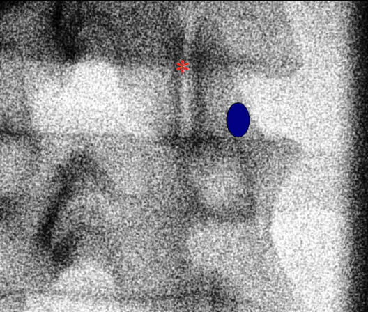 Figure 1. A fluoroscopic image of the lumbar facet joint. The blue circle highlights the medial branch target zone. The red asterisk indicates the facet joint.
Fluoroscopic Guided Lumbar Medial Branch Block
The patient is placed in the prone position under the fluoroscopy machine. For the L1 to L4 medial branches, the nerve is anesthetized as follows. The C-arm typically has a 25-35° oblique angulation. An oblique radiograph is obtained which demonstrates the junction between the superior articular and transverse processes (Figure 1). The needle is advanced towards the junction where the medial branch crosses the neck of the superior articular process and the upper border of the transverse process (Figure 1).[17] When the L5 posterior ramus needs to be anesthetized, the block is performed at the junction of the ala of the sacrum and the superior articular process of S1. For diagnostic purposes, once the needle is in appropriate position, 0.3-0.5 mL of an appropriate local anesthetic solution is injected to anesthetize the target nerve after negative aspiration. Some recommend injecting a test dose of contrast medium to test for possible vascular uptake prior to local anesthetic injection.[15] To anesthetize a specific joint, the medial branches must be anesthetized from the same vertebral level and also the descending branch from the vertebral level above. For example, to anesthetize the L3-L4 facet, the L2 and the L3 medial branches must be anesthetized.
Fluoroscopic Guided Lumbar Intra-articular Facet Injection
Facet joint intra-articular injections performed under fluoroscopy typically require an oblique rotation from 10° to 40° to obtain the best visualization of the joint space. A spinal needle is inserted into the joint with a coaxial technique. Contrast is injected to confirm intra-articular placement. The facet joint holds only a limited volume, 1–2 mL.
Ultrasound Guided Techniques
Sonoanatomy
In order to visualize the appropriate structures for lumbar medial branch blocks, a low frequency curved array transducer (2-6 MHz) is needed.18 Prior to an ultrasound guided procedure, it is important to have an understanding of the sonographic anatomy of the lumbar spine (Figure 2).
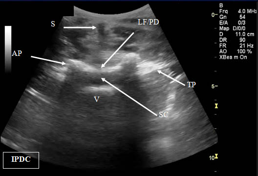 Figure 2. Transverse (cross axis) sonogram of the lumbar interspace. At times it may be difficult to distinguish the ligamentum flavum from the posterior dura. LF/PD = Ligamentum Flavum/Posterior Dura Complex. SC = Spinal Canal. V = Vertebral Body. S = Shadow of the Spinous Process. T= Transverse Process. AP = Articular Process.
The views utilized to define the sonoanatomy of the lumbar facet joint are the cross axis and the long axis views (Figure 3). In the long axis view the appropriate level of the spine can be identified. When the long axis view is true midline the spinous processes will be seen.
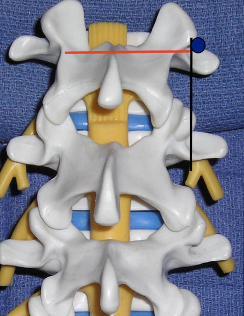 Figure 3. The ultrasound views (transducer locations) utilized for lumbar medial branch blocks: cross axis (red line) and long axis (black line) views. The blue circle indicates the desired target point for the lumbar medial branch block.
As the transducer is moved laterally, the bony structures become deeper and progress first to the articular pillars and then to the transverse processes. The cross axis view demonstrates the step-off deformities between the spinous, superior articular, and transverse processes (Figure 4). In some cases, the facet joint can be visualized in the cross axis view. The anatomical landmarks for the L5 dorsal ramus can be difficult to visualize secondary to bony artifact from the iliac crest (Figure 5).
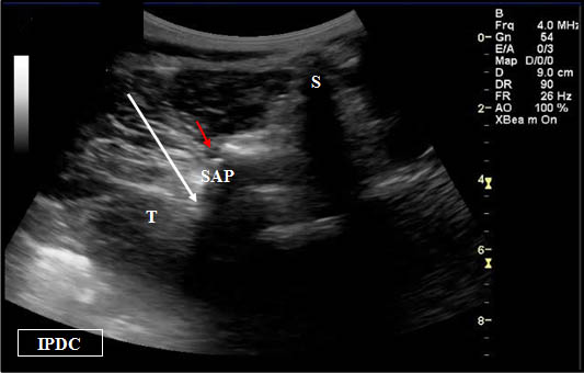
Figure 4. Sonographic cross axis view demonstrating the spinous, transverse, and superior articular processes. The white arrow demonstrates the needle pathway for blockade of the lumbar medial branch. Red arrow = Zygapophysial Joint. S = Spinous Process. SA = Superior Articular Process. T = Transverse Process.
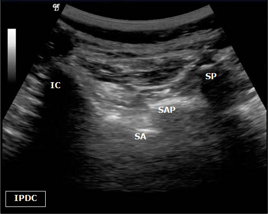 Figure 5. Sonoanatomy at the level of the L5 dorsal ramus. IC = Iliac Crest. SP = Spinous Process. SAP = Superior Articular Process. SA= Sacral Ala.
Ultrasound-Guided Lumbar Medial Branch Blocks
First, the patient is placed in the prone position with a pillow under the abdomen to reduce lumbar lordosis. The appropriate level of the lumbar spine is identified under the long axis view. Once the sacrum is identified in the long axis view (Figure 6), each respective lumbar level can be labeled. The appropriate level can also be verified in the cross axis view. In the cross axis view, the transducer is started in the caudad position over the sacrum. The transducer is slowly moved cephalad until the first bony protuberance is seen, the S1 median crest of the sacrum (Figure 7). This level is then used to count the spinous processes as the transducer is moved cephalad over the appropriate vertebral level.
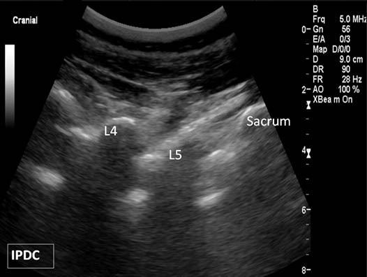
Figure 6. Paramedian oblique sagittal sonogram of the lumbar spine.
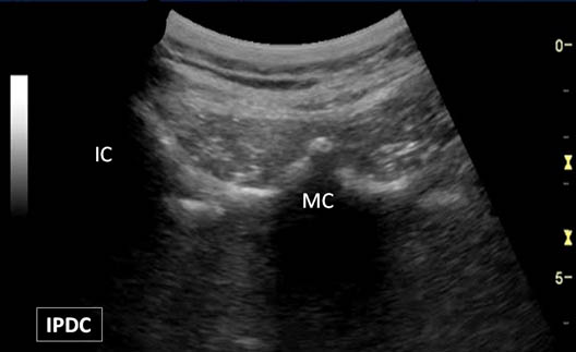 Figure 7. A bony protuberance representing the S1 median crest (MC) of the sacrum. IC = Iliac Crest.
Initially, the long axis view is obtained over the midline. When the transducer is over the true midline, the spinous processes will be close to the skin level. As the transducer is moved laterally, the view progresses from the articular pillars to the transverse processes. The transverse processes are located deeper than the level of the articular pillars. The level to be anesthetized is centered. The transducer is then rotated 90° to the cross axis view (Figure 4). The step-off deformities are seen between the spinous process, the superior articular process and the transverse process. To place the needle at the cranial junction of the transverse process and the neck of the superior articular process, it is advisable to scan progressively cephalad in the cross axis (transverse) until the transverse process is no longer visible in the field-of-view. Once this position is located the transducer is then moved slightly caudal to bring the transverse process back into view. Often this final cross axis view corresponds to the interlaminar space. Under real-time ultrasound guidance with an in plane technique, a 20 to 22-gauge spinal needle is inserted from lateral to medial (Figure 8). The insertion angle is approximately 45° to 60° to the skin. The needle is directed down to the junction between the superior articular process and the superior border of the transverse process.
Figure 8. A needle (arrows) is being placed at the target point for a lumbar medial branch block. S = Spinous Process. T = Transverse Process. SA = Superior Articular Process.
Once bony contact is reached, the transducer is rotated back to the long axis view to confirm that the needle tip is at the cranial edge of the transverse process (Figure 9). Often the needle tip is difficult to visualize with the long axis view because the needle is now out-of-plane. Agitation of the needle often assists in the visualization. On the parasagittal view of the transverse processes, the needle tip often needs to be readjusted to the appropriate position. If the needle tip still cannot be seen, the transducer is then directed back to the cross axis view and the needle tip is walked cephalad along the grove between the transverse and superior articular processes. Once the needle begins to slip towards the intervertebral foramen, the upper border has been passed. The needle is then walked caudad until bony contact is achieved. The above steps need to be taken to avoid transforaminal advancement of the needle. Local anesthetic is then injected to anesthetize the respective medial branch. The local anesthetic should be injected in the cross axis view. If a hypoechoic expansion is not seen, the needle tip may be located in the intravascular space.
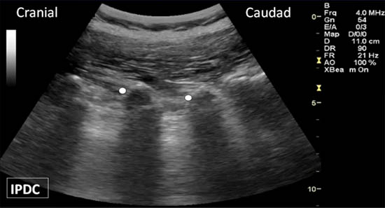
Figure 9. The long axis view of the transverse processes. Appropriate needle location is indicated by the white dots.
Ultrasound-Guided Intra-articular Facet Injection
The patient is placed in a prone position with a pillow under the abdomen to remove the lumbar lordosis. A low-frequency curved array transducer is utilized. The targeted lumbar vertebral joint level is identified with the longitudinal axis paravertebral sonogram. The sacrum is used as the landmark for counting. The target vertebral level is identified and centered under the ultrasound beam. The cross axis view is obtained by rotating the transducer 90°. Adjustments are made in transducer alignment to identify the facet joint between the inferior and superior articular processes (Figure 4). The target point is the middle portion of the joint. A 20-gauge needle is advanced in plane from lateral to medial. In individuals with significant degenerative changes accessing the joint can be challenging.
Literature Review
Ultrasound Guided Lumbar Medial Branch Block
Greher et al.[18] developed an ultrasound method for the lumbar medial branch block through a three-part study including cadaver, volunteer, and clinical case series sections. An ultrasound guided technique was developed in a cadaver model and then clinically tested at the L3, L4, and L5 vertebral levels (medial branches L2, L3, and L4). Based on the cadaver model, the low-frequency curved array transducer (2 to 6 MHz) provided the best visualization of the desired target points. The medial branches were not directly visualized with any of the transducers. The L5 dorsal ramus block was not evaluated. For the volunteer portion of the study, the median body mass index was 23 kg/m2 (range 19-36 kg/m2), and the median age was 36 years (range 23-67 yr). Although in the one individual with a body mass index of 36 kg/m2 the view was considered sufficient for the needed anatomical landmarks, this portion of the study may demonstrate results mainly for individuals with ideal body mass indexes at younger ages. In the clinical portion of the study, 89% of the needles were placed correctly with the remaining three needles within 5 mm of the radiologically defined target point. It should be pointed out that the authors utilized 21-gauge 8 cm long needles in the clinical case series. Patient acceptance and discomfort to the procedure was not evaluated. Future studies in comparison to fluoroscopy with smaller gauge needles are warranted for these measures.
Greher et al[19] also studied the above developed technique in a cadaver model with post-procedure computed tomography scans to assess accuracy of needle placement. Correct needle placement was confirmed in 90% (45 of the 50 needle placements). For the remaining 10%, the needles were within 5 mm of desired target which was the groove at the cephalad margin of the transverse process and adjacent to the superior articular process. Following needle placement, 1 mL of contrast dye was injected to determine the spread of the injectate. 14% of the cases had paraforaminal spread. Epidural spread and intravascular injection occurred 10% and 4% of the time, respectively.
In a clinical study with fluoroscopy control for ultrasound-guided lumbar medial branch blocks in 20 patients with a median age of 57 ±13 years and body mass index of 22.8 ± 3.1, 96 of 101 needle tips were positioned correctly (95% success rate).20 The average time for needle placement was 5 ± 1 minutes. Furthermore, in 39 of the 101 placed needles, the tip position could not be verified on the longitudinal paravertebral view which is used to confirm the appropriate position of the needle tip on the cephalad margin of the transverse process. Again, in this study, the L5 dorsal ramus block was not evaluated.
Recently, Rauch et al.[21] studied the feasibility of performing ultrasound-guided lumbar medial branch blocks in obese patients (body mass index > 30 kg/m2). In this patient population needle placement occurred correctly in only 62% of cases (52/84 blocks). Based on these results the authors concluded that ultrasound guidance cannot be used as the sole visualization technique in individuals with large body mass indexes. The success rate was lowest at the L5 dorsal ramus secondary to bony artifact and inability to visualize the needle at the depth of the target.
Ultrasound has some advantages over fluoroscopy for medial branch blocks and the most significant benefit is a reduction in radiation exposure. Possible limitations also exist for the ultrasound-guided technique as highlighted in the above studies. These include (1) the inability to correctly visualize the target in obese individuals, (2) the inability to detect intravascular injection, (3) a longer procedure time, and (4) the need for larger gauge needles. Furthermore, additional studies are needed to determine the utility of ultrasound for targeting the L5 dorsal ramus in individuals with body mass indexes in the ideal range (22–28 kg/m2).
Ultrasound Guided Lumbar Intra-articular Facet Injection
In a cadaver model Galiano et al.[22] developed an ultrasound-guided approach for lumbar intra-articular facet injections. The distance to the joint space measurements were compared to those obtained by computed tomography (CT). The Pearson’s coefficient of correlation was 0.86 between the ultrasound and CT measurements. Based on these encouraging results, the same group developed a prospective randomized clinical trial for ultrasound-guided verses computed tomography controlled facet injections.[23] A total of 40 patients were enrolled. 16 of the 20 patients randomized to the ultrasound group were deemed to have clearly visualized ultrasound anatomical landmarks. In these 16 patients the accuracy of needle placement was 100%. Two of the 20 subjects randomized to ultrasound group were not deemed candidates for the ultrasound technique secondary to the inability to clearly visualize the lumbar facet joints. These 2 individuals had body mass indexes of 28.3 and 32.9 kg/m2. The procedure was faster with ultrasound and occurred with less radiation in comparison to CT-guided injections.
Commentary
Classification of Procedures
The lumbar medial branch block is considered an intermediate level (2) block because the target lies deep and there is a potential risk of reaching the intervertebral foramen. The lumbar zygapophysial periarticular facet block is considered a basic level (1) block.
Additional Remarks
Lumbar Medial Branch Block
From the anatomical perspective, it is important to note that the lumbar medial branch lies in a tiny osseo-fibrous tunnel (with a ligamentous roof) between the mamillary and accessory processes of a vertebra before it divides into terminal branches and before it loses bony contact. The accessory process is located in the center or lower part of the root of a transverse process. The mamillo-accessory ligament runs from the ipsilateral mamillary and accessory processes on each respective side of a lumbar vertebral body. Block failure may occur if a medial branch block is performed too caudally at the level of the mamillo-accessory ligament. This is particularly true when the ligament is ossified (a fairly common occurrence).
Common Mistakes
It is important to obtain a clear view of the bony shadow of the transverse process and the articular process in the transverse plane. This is more important than obtaining a simultaneous view of the bony contour of the superior articular process. The use of a linear transducer is inappropriate even in slim individuals because of its limited field of view and the depth of penetration. At times, it can be difficult to obtain the appropriate short axis view secondary to a narrow and/or short transverse process.
Lumbar Zygapophysial Periarticular Facet Block
Facet articulations are relatively tight diarthroses with tense ligamentous restriction. The facet joints in the lumbar spine vary in shape and direction. Lumbar facet joints often have an oblique orientation. In addition, the lumbar facet joint orientation demonstrates inter-individual and intra-individual variability. At a specific lumbar level in an individual, variation may also exist from side to side. In the transverse plane, the lumbar facets may be curved. The curvature of the joint may resemble a C or J-shape. In practice, ultrasound-guided lumbar zygophysial joint injection should be regarded primarily a periarticular injection. Furthermore, there are recognized malformations of the facet joints e.g. an absence of a joint due to fused vertebrae.
The hypoechoic or anechoic space between the articular processes represents the space between the lateral aspect of the inferior articular process (which is most posterior) and the medial aspect of the superior articular process. This space does not represent the entire joint but rather the posterior entrance point into the joint. Under ideal conditions, the covering ligaments (i.e., the joint capsule) may be visualized as a hyperechoic structure. It is important to note that while the facet joints can be reliably visualized with ultrasound, the joint space itselfcannot be visualized due to the bony surrounding and poor beam penetration. Common mistakes of this block are related to the use of inappropriate transducers, misinterpretation of “other gaps” as target (e.g. between osteophytes) and searching a gap that may not exist.
References
- Schwarzer AC, Aprill CN, Derby R, Fortin J, Kine G, Bogduk N. Clinical features of patients with pain stemming from the lumbar zygapophysial joints. Is the lumbar facet syndrome a clinical entity? Spine 1994;19:1132-1137.
- Schwarzer AC, Wang SC, Bogduk N, McNaught PJ, Laurent R. Prevalence and clinical features of lumbar zygapophysial joint pain: a study in an Australian population with chronic low back pain. Ann Rheum Dis 1995;54:100-106.
- Toyone T, Ozawa T, Kamikawa K, Watanabe A, Matsuki K, Yamashita T, et al. Facet joint orientation difference between cephalad and caudad portions: a possible cause of degenerative spondylolisthesis. Spine (Phila Pa.1976) 2009;34:2259-2262.
- Bogduk N. Clinical Anatomy of the Lumbar Spine and Sacrum. Fourth edition ed.: Elsevier Churchill Livingston; 2005.
- Taylor JR, Twomey LT. Age changes in lumbar zygapophyseal joints. Observations on structure and function. Spine (Phila Pa.1976) 1986;11:739-745.
- Adams MA, Hutton WC. The mechanical function of the lumbar apophyseal joints. Spine (Phila Pa.1976) 1983;8:327-330.
- Adams MA, Hutton WC. The effect of posture on the role of the apophysial joints in resisting intervertebral compressive forces. J Bone Joint Surg Br 1980;62:358-362.
- Schmidt H, Heuer F, Wilke HJ. Interaction between finite helical axes and facet joint forces under combined loading. Spine (Phila Pa.1976) 2008;33:2741-2748.
- Lau P, Mercer S, Govind J, Bogduk N. The surgical anatomy of lumbar medial branch neurotomy (facet denervation). Pain Med 2004;5:289-298.
- Bogduk N. The lumbar mamillo--accessory ligament. Its anatomical and neurosurgical significance. Spine (Phila Pa.1976) 1981;6:162-167.
- Bogduk N. The innervation of the lumbar spine. Spine (Phila Pa.1976) 1983;8:286-293.
- Schwarzer AC, Aprill CN, Derby R, Fortin J, Kine G, Bogduk N. The prevalence and clinical features of internal disc disruption in patients with chronic low back pain. Spine (Phila Pa.1976) 1995;20:1878-1883.
- Schwarzer AC, Wang SC, O'Driscoll D, Harrington T, Bogduk N, Laurent R. The ability of computed tomography to identify a painful zygapophysial joint in patients with chronic low back pain. Spine (Phila Pa.1976) 1995;20:907-912.
- Chou R, Loeser JD, Owens DK, Rosenquist RW, Atlas SJ, Baisden J, et al. Interventional therapies, surgery, and interdisciplinary rehabilitation for low back pain: an evidence-based clinical practice guideline from the American Pain Society. Spine (Phila Pa.1976) 2009;34:1066-1077.
- Bogduk N. Evidence-informed management of chronic low back pain with facet injections and radiofrequency neurotomy. Spine J 2008;8:56-64.
- Kaplan M, Dreyfuss P, Halbrook B, Bogduk N. The ability of lumbar medial branch blocks to anesthetize the zygapophysial joint. A physiologic challenge. Spine (Phila Pa.1976) 1998;23:1847-1852.
- Bogduk N editor. Practice Guidelines for Spinal Diagnostic and Treatment Procedures. First Edition ed. San Francisco, California: International Spine Intervention Society; 2004.
- Greher M, Scharbert G, Kamolz LP, Beck H, Gustorff B, Kirchmair L, et al. Ultrasound-guided lumbar facet nerve block: a sonoanatomic study of a new methodologic approach. Anesthesiology 2004;100:1242-1248.
- Greher M, Kirchmair L, Enna B, Kovacs P, Gustorff B, Kapral S, et al. Ultrasound-guided lumbar facet nerve block: accuracy of a new technique confirmed by computed tomography. Anesthesiology 2004;101:1195-1200.
- Shim JK, Moon JC, Yoon KB, Kim WO, Yoon DM. Ultrasound-guided lumbar medial-branch block: a clinical study with fluoroscopy control. Reg Anesth Pain Med 2006;31:451-454.
- Rauch S, Kasuya Y, Turan A, Neamtu A, Vinayakan A, Sessler DI. Ultrasound-guided lumbar medial branch block in obese patients: a fluoroscopically confirmed clinical feasibility study. Reg Anesth Pain Med 2009;34:340-342.
- Galiano K, Obwegeser AA, Bodner G, Freund M, Maurer H, Kamelger FS, et al. Ultrasound guidance for facet joint injections in the lumbar spine: a computed tomography-controlled feasibility study. Anesth Analg 2005;101:579-83.
- Galiano K, Obwegeser AA, Walch C, Schatzer R, Ploner F, Gruber H. Ultrasound-guided versus computed tomography-controlled facet joint injections in the lumbar spine: a prospective randomized clinical trial. Reg Anesth Pain Med 2007;32:317-322.
Leave a commentOrder by
Newest on top Oldest on top