Fluoroscopy and Radiation Safety
Authors
Honorio T. Benzon, MD
Professor
Brian A. Chung, MD
Assistant Professor
Department of Anesthesiology
Northwestern University Feinberg School of Medicine
Chicago, IL
Needle Placement With and Without Fluoroscopy
Incorrect needle placements have been demonstrated when epidural steroid injections are performed without fluoroscopic guidance. These incorrect placements occurred in 25% of caudal and 30% of interlaminar epidural steroid injections when performed by an experienced anesthesiologist and an orthopedic surgeon.[1] Another study showed inaccurate needle placement in 17% of epidural injections performed by experienced anesthetists using the interlaminar technique, 85% of the injections were in the lumbar area.[2]
For caudal injections, “experienced radiologists” incorrectly place the needle in 38% of their epidural injections.[3] Success rates appear to be related to the experience of the radiologist however. Radiologists who performed less than 10 epidurals had a 48% failure rate. In a prospective observational study, senior PM&R physicians had a 74% success rate on their attempt, 88% when the landmarks were identified easily.[4] They noted that the most common site of incorrect needle placement was along the subfascial plane posterior to the sacrum. A study on the use of fluoroscopy in caudal injections implied higher success rates. Caudal epidural steroid injections done by radiologists under fluoroscopy resulted in a success rate of 97.3%.[5] The authors recommended that epidurogram be performed to document position of the needle and to confirm that the medications are not injected intrathecally or intravenously.
For cervical epidural steroid injections, a multicenter, retrospective study showed 47% success on first attempt; a second attempt was required in 63% of the patients.[6] It was noted that there was unilateral contrast spread in 51% of the injections.
For post-laminectomy patients, anesthesiologists successfully placed the epidural in 92% of the attempts. The number of attempts to successfully enter the epidural space was 2+1.[7] Even though the success rate was high, it was noted that the needle was placed 1 or 2 spaces above or below predetermined level in 53% of the attempts and that the contrast reached the level of pathology in only 26% of the cases
In a national survey of pain medicine physicians, it was noted that 73% of private practices use fluoroscopy compared to 39% of academic institutions.[8]
Fluoroscopy Machine
X-rays are generated by a current, measured in milliamperes (mA), passing through an electrically heated negatively charged filament (the cathode). This process produces electrons. The high voltage (kilovolt peak, kVp) passes through the x-ray tube towards the positive electrode (anode). The electrode-anode interaction produces energy that is converted to x–radiation. The x-ray radiation that passes through the body enters the image intensifier where it is converted to a visible image that is displayed on the monitor screen (Figure 1).
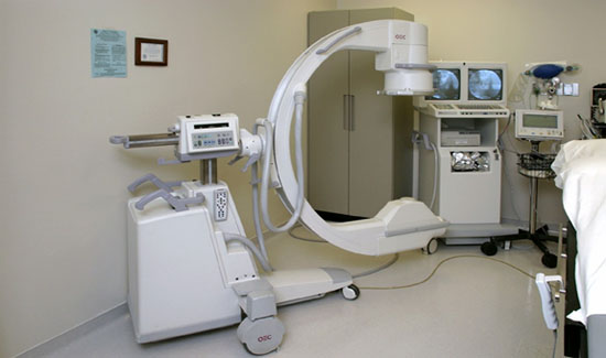
Figure 1. A typical fluoroscopy machine. The x-ray tube occupies the inferior portion of the C-arm while the image intensifier is at the superior portion.
The quality of picture contrast depends on the balance between the kVp and the tube current. Increased kVp increases the penetrability of the x-ray beam and decreases the contrast, producing brighter pictures. Higher kVp and tube current increase the total amount of x-ray radiation (see control panel of the fluoroscopy machine, Figure 2). ABC or Automatic Brightness Control system (Figure 3) occurs when the computer automatically analyzes the picture contrast and makes the appropriate tube current adjustments balancing picture contrast and patient safety.
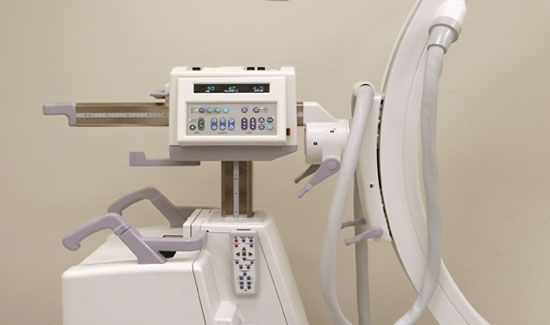
Figure 2. Control panel of the fluoroscopy machine
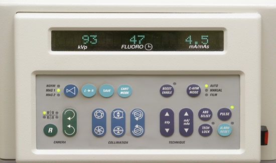
Figure 3. Detailed picture of the control pane
Radiation Safety
Rad (radiation absorbed dose) is the unit of measure that expresses the amount of energy deposited in tissue from an ionizing radiation source. Gray (Gy) is the term used under the International System of units (SI) as the principal unit for measurement of ionizing radiation dose. It is defined as the quantity of radiation which results in an energy deposition of 1 joule per kilogram (1 J kg-1) within the irradiated material. 1 Gy = rad; 1 Gy = 1000 mGy.
Radiation Equivalent Man (rem) is used to predict the biological effects from different types of radiation. The unit of dose equivalent, under the SI system, is sievert (Sv). 1 Sv = 100 rem; 1 rad = 1 rem.
The biological effects of radiation are caused by the ionization of water molecules within cells, producing highly reactive free radicals that damage macromolecules such as DNA. The maximum permissible dose (MPD) is the upper limit of allowed radiation dose one may receive without the risk of significant side effects (Table 1). The annual whole-body dose limit for physicians is 50 mSv.
| Organ/Area | Annual Maximum Permissible Dose | |
|---|---|---|
| Lens of eye | 15 rem | 150 mSv |
| Thyroid | 50 rem | 500 mSv |
| Gonads | 50 rem | 500 mSv |
| Extremities | 50 rem | 500 mSv |
| Whole Body | 50 rem | 500 mSv |
The minimum amount of radiation to produce effects range from 200 rads for the formation of cataracts to 5,000 to 10,000 rads to cause cerebral edema (Table 2). The period when the fetus is most sensitive to radiation is between 8 to 15 weeks gestation when the rate of proliferation of DNA within the brain is at a maximum. The maximum permissible dose is 0.5 rem or 5 mSv to the fetus.
| Organ | Dose | Result |
|---|---|---|
| Eye lens | 200 | Cataract |
| Skin | 500 | Erythema |
| Skin | 700 | Alopecia |
| Whole body | 200–700 | Hematopoetic failure (4–6 weeks) |
| Whole body | 700–5,000 | Gastrointestinal failure (3–4 days) |
| Whole body | 5,000–10,000 | Cerebral edema (1–2 days |
Radiation Protection
Two principles should be followed in reducing radiation exposure to the patient and the medical personnel when performing interventional pain management procedures:
- ALARA = As Low As Reasonably Achievable; and,
- ALARP = As Low As Reasonably Practicable
Radiation Protection of the Patient
Preferably, the fluoroscopy machine should be equipped with a laser pointer. This is attached to the image intensifier (Figure 4) and helps identify the site of injection and reduces the number of preliminary views.
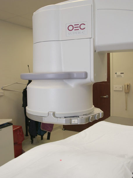
Figure 4. A laser pointer is attached to the image intensifier
The beam-on time should be minimized since radiation exposure increases linearly with time and the total exposure is equal to the exposure rate multiplied by the time. One should rely on freeze frames as frequently as possible. As there is no automatic stop once a quality image is produced, care must be taken to manually stop the imaging process.
The x-ray tube should be kept as far away from the patient as possible since increasing distance from x-ray tube to patient reduces skin burns. The image intensifier should be as close to the patient as possible to maintain image quality. Use tight collimation (thin metal shield over x-ray tube orifice) when showing the site of injection (see Figure 3). This reduces the surface area being irradiated and the amount of x-ray received by the patient. In addition, this will improve the image as there will be less scatter that will degrade the image that reaches the intensifier.
The use of magnification should be limited as much as possible since the dose the patient receives must increase in order to display the image with the same quality but at a larger size.
Radiation Protection of the Personnel
Reduction of radiation exposure of personnel is based on maximizing the distance from the source of x-ray, minimizing the time or duration of x-ray exposure, and creating physical protection from the radiation.
The major source of radiation is the patient or the fluoroscopy table which serves as conduits for scattered radiation. The patient dose and subsequent scatter should be reduced by decreasing the x-ray tube current to the lowest possible level compatible with a good image. The ABC system works to do this automatically.
Only necessary personnel should be in the fluoroscopy room and the personnel should be notified before the fluoroscopy is turned on. The beam-on time should be kept to a minimum. Pulse images can also be used, as opposed to continued live images, to decrease exposure.
The personnel should step back from field when the fluoroscopy is activated since the intensity of ionizing radiation decreases exponentially as the distance from the source is increased. Since the scatter radiation is 2-3 times higher at side of x-ray tube, the physician should preferably stand on the side of image intensifier when lateral views are taken. Note that the image intensifier has a lead-plastic apron attached to its edge which absorbs much of the scattered radiation emerging from the upper side of the patient & shields the radiologist/interventional pain physician. This arrangement assumes that the x rays are traversing through the patient’s body. If there was no patient in between the xray tube and image intensifier then the personnel on the side of the image intensifier would get a direct hit of the radiation.
In conventional undercouch fluoroscopy, the x-ray tube is located beneath the table while the image intensifier is above the table (Figure 5). Most of the scattered radiation is in the downward direction & is absorbed in the floor or side panels of the table. In overcouch fluoroscopy, the positions of the x-ray tube and image intensifier are reversed. For oblique & lateral views, it is difficult to get adequate shielding for medical personnel.
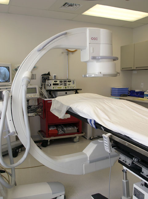
Figure 5. An overcouch arrangement of the fluoroscopy machine
Barriers and Shielding
Barriers or screen are ideal for absorbing x-rays; these are usually employed in orthopedic and urology operating room suites. There are three categories: fixed, mobile, and personal. Fixed barriers include the thickness of the walls (lead equivalence, or LE of 1-3 mm), doors, & protective cubicles. Mobile barriers are appropriate during fluoroscopy procedures where a member of the staff needs to remain near the patient. Personal barriers include lead aprons, gloves, thyroid shields, and glass spectacles.
Lead Aprons
Lead aprons should be worn and stored properly. They should not be folded since this produces creases that may create breaks in the protective lead barrier. “Wrap-around” lead aprons are useful when the medical personnel spend a lot of time with their back turned away from the patient. For reasons of weight, lead aprons generally have shielding equivalence equal to 0.25 – 0.5 mm lead barrier & so will only attenuate the primary beam. Note that lead aprons absorb 90-95%, not 100%, of the scattered radiation that reaches it (Table 3).
Table 3. Percentage Primary X-ray Beam Transmission for Kilovoltages and Lead Aprons
| Lead thickness | Single-phase generator (1 or 2 pulse) | ||
|---|---|---|---|
| 75 kVp | 100 kVp | 125 kVp | |
| 0.22 | 4.5 | 12.1 | 12.8 |
| 0.44 | 0.7 | 3.7 | 5.1 |
| 0.5 | < 0.1 | 3.1 | 4.4 |
| 0.72 | < 0.1 | 1.4 | 2 |
| 1 | < 0.1 | 0.3 | 0.6 |
Lead Gloves
The commonly used lead-rubber gloves have a minimum lead equivalence of 0.25 mm; thicker gloves make manipulations more difficult. The wearing of gloves may give the physician a false sense of security since it may increase x-ray exposure. When the fluoroscopy is in ABC mode, the machine senses the poor contrast between the bones of the gloved hand and the surrounding soft tissue—the ABC system automatically adjusts (increases) the mA setting to produce a better contrast image i.e., a higher radiation dose is required.
Lead Glasses
Leaded glasses with side shields may reduce the risk of cataract formation. The effectiveness of glass spectacles may be overrated since ordinary eyeglasses may give adequate reduction in the radiation dose that reaches the lens of the eye.
Monitoring
Federal & state regulations require that anyone who works in a station where or she may receive over 25% of the allowable quarterly limit (1.25 rem or 1250 mrem) must be supplied with a monitoring equipment, i.e. film badge.
A film badge is a pack of photographic film that measures radiation exposure with a densitometer, which detects both the quantity and the quality of radiation (beta, gamma radiation). There are two film badges that are usually worn: a) a collar badge, which is worn outside the apron on the upper portion of body, approximates exposure to lens of eye; and, b) a waist badge worn behind the apron, which represents the actual dose to the gonads and major blood-forming organs.
The film is easily damaged by pen or by moisture and cannot be used for periods exceeding 8 weeks because the image fades. The badges should be returned on time since old badges give inaccurate results. Reports are issued in the form of monthly computer printouts (Figure 6).
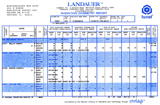
Figure 6. Radiation Dosimetry Report
References
- White AH, Derby R, Wynne G. Epidural injections for the treatment of low back pain. Spine 1980;5:78-86
- Mehta M, Salmon N. Extradural block. Confirmation of injection site by x-ray monitoring. Anaesthesia 1985;40:1009-12
- Renfrow DL, Moore TE, Kathol MH, et al. Correct placement of epidural steroid injections: Fluoroscopic guidance and contrast administration. Am J Neuroradiol 1991;12:1003-7
- Stitz MY, Sommer HM. Accuracy of blind versus fluroscopically guided caudal epidural injection. Spine 1999;24:1371-1376
- El-Khoury GY, Ehara S, Weinstein JN, Montgomery WJ, Kathol MH. Epidural steroid injection: A procedure ideally performed with fluoroscopy control. Radiology 1988;168:554-557
- Stojanovic MP, Vu TN, Caneris O, Slezak J, Cohen SP, Sang CN. The role of fluoroscopy in cervical epidural steroid injections. Spine 2002;27:509-514
- Fredman B, Ben Nun M, Zohar E, Iraqi G, Shapiro M, Gepstein R, Jedeikin R. Epidural steroids for treating “failed back surgery syndrome: Is fluoroscopy necessary” Anesth Analg 1999;88:367-372
- Cluff R, Mehio AK, Cohen SP, Chang Y, Sang CN, Stojanovic MP. The technical aspects of epidural steroid injections: A national survey. Anesth Analg 2002;95:403-408
Additional References for Fluoroscopy and Radiation Safety
- Broadman L.Radiation safety. In Raj PP et al (eds.) Practical Management of Pain. St. Louis: Mosby. 2000, pp 834-837
- Robinson A. Diagnostic protection and patient doses in diagnostic radiology. In Grainger & Allison’s Diagnostic Radiology: A Textbook of Medical Imaging. Grainger RG, Allison D (eds.) New York: Churchill-Livingstone, 1997, pp 169-189
- Goetz BB, Murphy CH. Radiation safety. In Murphy CH, Murphy MR (eds.). Radiology for Anesthesia and Critical Care. New York: Churchill-Livingstone, 1987, pp 257-262
- Fishman SM, Smith H, Meleger A, Seibert JA. Radiation safety in pain medicine. Reg Anesth Pain Med 2002;27:296-305
- Benzon HT. Fluoroscopy and radiation safety. In: Benzon HT, Raja S, Molloy RE, Liu SS, Fishman FM (eds.). Essentials of pain medicine and regional anesthesia. New York: Elsevier-Churchill Livingstone, 2005:516-524
- Rathmell JP, Fishman SM. Radiation safety and use of radiographic contrast agents in pain medicine. In Benzon HT, Rathmell J, Wu C, Turk DC, Argoff C (eds) Raj’s Practical Management of Pain. 4th Ed. New York: Elsevier – Mosby, 2008:1187-1197
Leave a commentOrder by
Newest on top Oldest on top