Ultrasound Sonoanatomy and Associated Interventional Procedures for Axial Structures
Author
David A. Provenzano, MD
President
Pain Diagnostics and Interventional Care
Sewickley, PA
Introduction
Recently, there has been significant interest in the utilization of ultrasound for chronic pain management procedures. Traditional visualization techniques for these procedures include fluoroscopy and computed tomography (CT). With fluoroscopic guided procedures the initial extrapolation of the position of soft tissues (i.e. muscles, blood vessels, and nerves) is based on their anatomic relationship to viewed bony structures. The interest in the use of ultrasound for chronic pain management procedures has grown from certain visualization advantages including the ability to see muscle layers, nerves, and blood vessels (Table 1).[1] Ultrasound allows for the elimination or reduction of radiation exposure for both the patient and physician. Additionally, real time needle advancement can be visualized with ultrasound. Limitations to current ultrasound technology exist, including narrow image windows, and acoustic shadow artifact which results in the inability to view structures deep to bony obstruction.
Table 1. Proposed Ultrasound Advantages and Limitations for Chronic Pain Procedures
| Advantages | Limitations |
|---|---|
|
|
In this review, the current application of ultrasound for axial visualization and specific guided blocks in chronic pain management will be described. A detailed understanding of anatomy is critical to the interpretation of the sonographic images. The anatomy and sonoanatomy will be described for each axial area.
Transducer Selection
The transducers needed for the visualization of axial structures include linear and curved array transducers (Figure 1).[2] The linear transducers assist in the visualization of superficial structures including nerves and blood vessels with small diameters. High-frequency linear transducers provide better resolution but offer less penetration. The use of linear array transducers in the cervical spine region allow for visualization of cervical medial branches, nerve roots, and some critical vascular structures.
Curved array transducers allow for the delineation of a greater region and for the visualization of deeper structures. Curved array transducers are utilized for lumbosacral spine ultrasound.
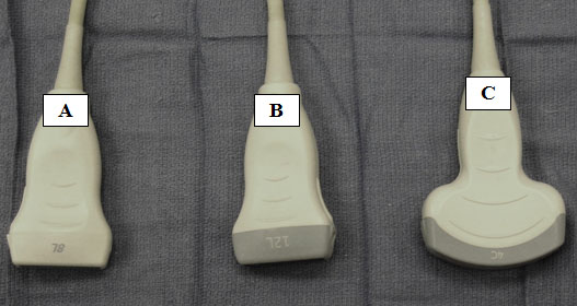
Figure 1. Medium (A) and high frequency (B) linear transducers. Low frequency curvilinear array transducer (C).
Cervical Facet and Medial Branch Blocks
Anatomy
The cervical spine has 7 vertebrae. C3-C6 vertebrae are similar in their bony characteristics. C1, C2, and C7 have specific anatomical characteristics. C1 is termed the atlas which articulates with the occiput and with C2 (axis). C1 and C2 form the atlanto-axial joint which is responsible for a significant amount of the movement associated with cervical rotation. The atlas lacks a body, and it articulates with the odontoid process (dens) from C2. C7 has a prominent spinous process.
We will focus on cervical facet joints 2 through 7 which are synovial joints with a fibrous capsule. Cervical facet joints are diarthrodial joints oriented in an oblique coronal plane. In the cervical spine the facet joints are oriented at approximately 45° to the transverse plane. Articular pillars join the superior and inferior articular facets. The C2-C3 facet is innervated by the third occipital nerve. The third occipital nerve is a superficial medial branch of the C3 dorsal ramus.[3] The remaining cervical facet joints are innervated by medial branches that arise from the dorsal primary rami and then progress around the respective articular pillar. Each cervical facet joint is innervated by two medial branches. The medial branches originate cephalad and caudad to the joint. The dorsal primary ramus also gives off a lateral branch which innervates the paraspinal muscles.
In the cervical region the medial branch of a particular level progresses around the same articular pillar. For example the C5 medial branch travels across the C5 articular pillar. Thus, the C5-C6 facet joint is innervated by the C5 and C6 medial branches. Typically, the third occipital nerve measures approximately 1.5 mm in diameter. The remaining cervical medial branches are less than 1 mm.[4] The cervical medial branches do not lie directly on the articular pillar and are often displaced from the bone by 1 to 2 mm.[4-5]
Sonoanatomy
A high frequency linear array transducer is needed for visualization of the cervical medial branches and facet joints. Multiple ultrasound techniques have been described to visualize the cervical facets and associated medial branches.[5-9] The first technique involves positioning the patient in the lateral decubitus position.[7] Initially the transducer is placed over the mastoid process in the longitudinal axis. The transducer position is optimized to view the transverse processes of C1 and C2. The vertebral artery between C1 and C2 can often be visualized. Next, the transducer is moved posteriorly and caudad in the longitudinal plane. The third occipital nerve is identified. The third occipital nerve exists 1 mm from the bony elements. Once the third occipital nerve has been identified and the associated C2-C3 facet, these landmarks can be used for counting as the transducer is moved caudad over the remaining cervical facet joints (Figure 2). The remaining cervical medial branches are identified around each respective neck of the articular pillar (i.e. depressed area). The nerves typically are hypoechoic structures with internal hyperechoic areas (Figure 3).
Lee et al.[5] developed a second technique for visualization of the cervical medial branches based on a cadaver study. The patient is placed in the prone position. First a long axis sagittal plane view is obtained. Once the appropriate articular pillow is identified, the transducer is rotated 90° to the axial plane. The axial plane scan provides a transverse image which demonstrates the articular pillar, the associated cervical medial branch, and the multifidus and the longissimus muscles. This technique was tested for cervical medial branch radiofrequency in cadavers. Successful neurotomy was confirmed in 30 of the 34 cervical medial branches
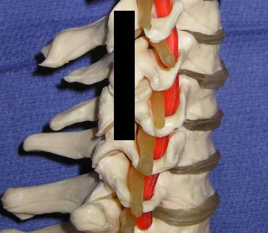
Figure 2. The black line delineates the longitudinal axis of the ultrasound beam in order to visualize the cervical facets and associated medial branches.
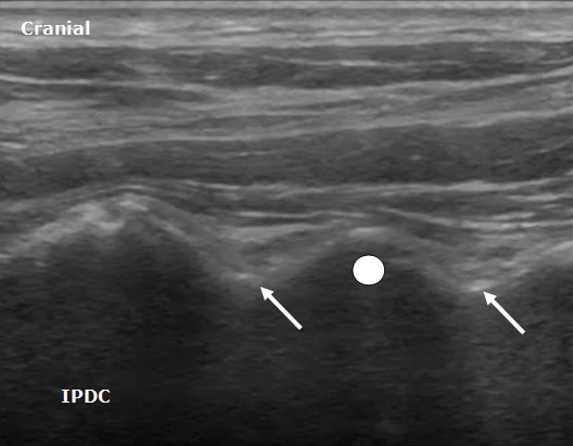
Figure 3. A longitudinal ultrasound image of the cervical spine demonstrating the cervical medial branches (arrows) and associated cervical facet joint (circle).
Ultrasound Technique For Cervical Medial Branch and Facet Intra-Articular Injection
After the cervical medial branches are identified by the above description, a needle is inserted out of plane (short axis).7 The needle is advanced until it is adjacent to the medial branch. After insuring the lack of vascular structures in the region of the needle with ultrasound imaging and negative aspiration, 0.3-0.5 mL of local anesthetic is injected. It is preferable to advance the needle from anterior to posterior since the neural foramen and vertebral artery are anterior to the cervical facets. Eichenberger et al.6 described in detail the sonographic visualization and the ultrasound-guided block specifically for the third occipital nerve. Needles were positioned correctly in 82% of cases.
Both the lateral and posterior approaches are used for ultrasound guided cervical facet intra-articular injections.[7-9] First, the appropriate level is identified based on the appearance of the spinous processes. C1 either lacks or has a rudimentary spinous process. Once C1 has been identified, the remaining levels can be labeled. In the posterior approach a midline longitudinal (sagittal) scan is obtained over the spinous processes. The transducer is moved laterally and progresses from the laminae to the facet column. The facet column (Figure 4) will appear as the characteristic “saw sign,” with the joint appearing as an anechoic area between the respective superior and inferior articular processes (hyperechoic lines). The needle is advanced in plane into the joint in the caudad to cephalad direction.
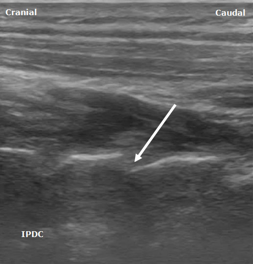
Figure 4. A posterior sagittal ultrasound image of the cervical facet column. The white arrow depicts the trajectory for needle insertion into the facet joint.
Cervical Spinal Nerves
Anatomy
The cervical spine consists of 7 cervical vertebrae and 8 pairs of cervical spinal nerves. The cervical plexus arises from the anterior rami from C1-C4. Here the focus will be on the C4, C5, C6, and C7 spinal nerves roots and the corresponding anatomy and sonoanatomy which aids in their identification under ultrasound guidance. The anterior rami of C5-C8 and T1 form the roots of the brachial plexus.
For the C3-C6 cervical vertebrae, general specific bony characteristics exist (Figure 5). Each vertebra consists of a body, transverse processes, and associated anterior and posterior tubercles, articular processes (i.e. lateral masses), groves for spinal nerves, pedicles, laminae, and spinous process. The transverse processes consist of anterior and posterior tubercles. The tubercles are connected by a sulcus of bone which the vertebral artery passes through the foramen transversarium and the corresponding spinal nerve root exits.[10] The cervical nerve roots exit through the neural foramen above their corresponding cervical vertebral body (i.e. the C6 cervical nerve root exits between C5 and C6) except for C8 nerve root which exists between C7 and T1. As the nerve roots exit the foramen they often divide into 2 or 3 divisions.[11]
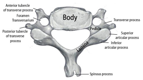
Figure 5. Illustration showing the relevant anatomy of a cervical vertebra for the C3 through C6 levels.
A traditional topographic landmark used to identify the C6 vertebral body is the cricoid cartilage. The C6 vertebra has a prominent anterior tubercle (Chassaignac's tubercle) with a shorter posterior tubercle. Large anatomical variability exists in the size and location of Chassaignac's tubercle. The cephalad-caudad dimension of the transverse process has been shown to have an average minimal breadth of only 6 mm at the C6 level.[12] At the C7 level there is a large posterior tubercle with either an absent or rudimentary anterior tubercle.[13]
It is important to recognize the critical vascular structures in the region of the cervical spine. These critical structures include the vertebral, inferior thyroid, ascending cervical, deep cervical and radicular arteries, which often are in the vicinity of specific cervical spinal nerves as they exit their respective foramen.[14-16] The inferior thyroid artery originates from the thyrocervical trunk. The ascending cervical artery, a small branch originating from the inferior thyroid artery, may pass over the transverse processes of C6 or C7.[15] The vertebral artery, which arises from the subclavian artery, passes anteriorly at the C7 level and enters the transverse foramen in 93% of cases at the C6 level.10 In the remaining cases, the vertebral artery enters the transverse foramen at C3 (0.2%), C4 (1.0%), C5 (5%) and C7 (0.8%).[10] In cadavers, the vertebral artery average diameter was 4 mm.[14] At the C7 level the vertebral artery is unprotected by bony elements (Figure 6).
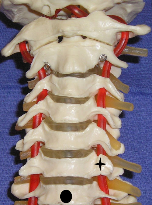
Figure 6. A cervical spine model demonstrating the large anterior tubercle of C6 (star) and the absent anterior tubercle at C7 (circle indicates body of C7).
Sonoanatomy
The sonoanatomy of the anterior and posterior tubercles associated with the transverse processes of the C4, C5, C6, and C7 vertebrae are used to identify their respective cervical nerve roots. The C7 vertebral body demonstrates an absent or rudimentary anterior tubercle with a prominent posterior tubercle (Figure 7). The anterior and posterior tubercles are seen as hyperechoic outlines with associated acoustic shadowing (hypoechoic area below). C6 has a sharp and prominent anterior tubercle and a shorter posterior tubercle. The nerve roots are viewed as homogeneous oval hypoechoic structures that exit through the transverse processes of the corresponding vertebral level. For example, the C6 nerve root will be seen between the anterior and posterior tubercles of the transverse process of C6 (Figures 8 & 9). The nerve roots differ in appearance from peripheral nerves below the clavicle which have a more hyperechoic appearance. As the transducer progresses to the more cephalad nerve roots, the anterior and posterior tubercles assume similar size characteristics (Figure 10) that have been referred to as the “2 humped camel sign.”[17] In approximately 90% of cases at the C7 level (Figure 7), the vertebral artery can be visualized prior to its entrance into the foramen at the C6 level.[10][18] Other important structures to visualize in the neck to assist with orientation include the thyroid, internal carotid artery, and jugular vein.
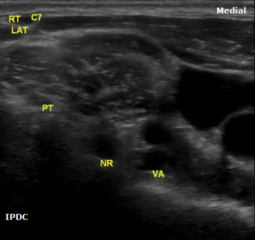
Figure 7. An axial image at the right C7 vertebral level demonstrating the prominent posterior tubercle and absent anterior tubercle. PT = Posterior Tubercle. NR = Nerve Root. VA = Vertebral Artery.
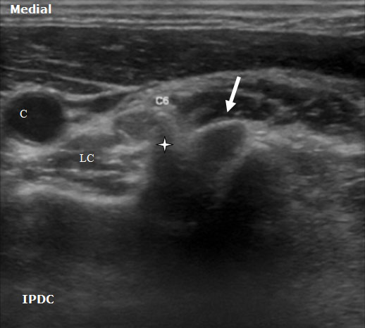
Figure 8. An axial ultrasound image at the C6 vertebral level demonstrating the nerve root (arrow) between the prominent anterior tubercle (star) and smaller posterior tubercle. LC= Longus Colli Muscle. C = Carotid Artery.
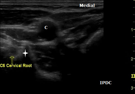
Figure 9. An axial ultrasound image at the C6 vertebral level demonstrating the nerve root and the prominent anterior tubercle (star). C = Carotid Artery.
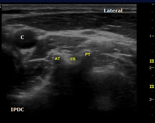
Figure 10. An axial image at the C5 level demonstrating the typical sonoanatomy of the anterior and posterior tubercles. AT = Anterior Tubercle; C = Carotid Artery; C5 = C5 Nerve Root; PT = Posterior Tubercle.
Ultrasound Technique for Cervical Nerve Root Block
The spinal nerve roots are identified on the basis of different morphologies of the transverse processes of each vertebral body. The patient is positioned in either the lateral decubitus position with visualized side up or in the supine position. In the supine position the cricoid cartilage should be palpated as a C6 landmark. Position a high-frequency linear array ultrasound transducer (5 to 12 MHz) lateral to this location. The transducer is applied transversely to the lateral aspect of the neck, and a short axis view is obtained. The carotid artery, internal jugular, vein, and thyroid should be identified. In the supine position the transducer is situated and moved laterally in the axial direction until the transverse processes are identified. The transverse processes are lateral to the carotid artery.
The level of the cervical spine is identified by the corresponding morphology of the transverse processes. At the C6 level the prominent anterior tubercle will be visualized with the longus colli muscle medially. The ultrasound transducer should be moved in a craniocaudal direction to further confirm the appropriate cervical level. The C7 level will have a prominent posterior tubercle, and the vertebral artery will be visualized medially in a majority of cases. As the transducer is moved cephalad from the C6 level, the anterior and posterior tubercles will assume a similar shape with the nerve root lying in between. In cases in which the identification of the cervical level is challenging, other sonoanatomy clues can be utilized.
If the patient is positioned in the lateral position, the transducer can be rotated in a vertical position near the posterior aspect of the neck to obtain a longitudinal midline scan. With this view the cervical spinous processes can be counted to identify the appropriate level. C1 lacks a spinous process. Once the appropriate level is identified, the transducer is then rotated back to the transverse axial view. When the nerve root and appropriate tubercle structures have been located, the transducer can be moved lateral so that one only sees these structures and the carotid artery is out of the field of view. Doppler sonography should be utilized to identify critical vessels within the vicinity of the cervical nerve roots. Due to bony dropout artifact, one is not able to trace the cervical nerve root or injected materials (i.e. radiographic contrast) within the foramen.
Ultrasound guidance has been utilized both for percutaneous ablation of cervical nerve roots 19 and selective nerve root blocks.[17] Significant and devastating complications have occurred with cervical transforaminal epidural steroid injections. Death, brain, and spinal cord injuries have occurred with these procedures20 causing individuals to question their continued performance.[21-23] Ultrasound guidance may have the ability to increase the safety of periradicular injections in the cervical spine due to its ability to detect vascular structures, although future efficacy and safety studies are needed. These procedures should only be performed by highly trained individuals with a detailed understanding and appreciation of the risk/benefit profile of the procedure for each respective patient.
Lumbar Medial Branch and Facet Injection
Zygapophysial (facet) joint mediated pain has been identified as a source of chronic low back. Below, the relevant anatomy, sonoanatomy, and the ultrasound guided interventional procedure for lumbar facet joint associated pain will be described.
Anatomy
The lumbar facet joints, pedicles, lamina, supraspinous and intraspinous ligaments, and the spinous processes form the posterior column of the spine. The lumbar facet joints are synovial joints formed by the superior and inferior articular processes of each respective vertebral body. In the lumbar spine the superior articular facet is anterior and lateral to the inferior articular facet. Facet joint orientation varies with spinal level and with the development of degenerative spondylolisthesis. Each joint has fibrous joint capsule, a synovial membrane, and hyaline cartilage. Fat also exists within the intra-articular space, and fat in the subcapsular pocket is attached to the fat in the extracapsular area. The adipose tissue pads and fibro-adipose meniscoids act as a protective barrier similar to a meniscus in a knee joint.[24] At its thickest interval the cartilage is approximately 2 mm. The facet joint only holds a small volume, typically 1–2 mL. As we age, areas of the cartilage develop erosion and thinning.[25] The facets contribute 40% to torsional load resistance in the lumbar spine. The facet joints assist in resisting forward translation, rotation and compressive loads, and shearing forces generated in the lumbar spine. By resisting these movements they assist in the protection of the intervertebral disc.[26]
The innervation for the lumbar facet joints arises from the L1 to L4 medial branches of the dorsal rami and the L5 dorsal ramus. As a spinal nerve exits the neural foramen it divides into a ventral primary ramus and a dorsal primary ramus. The L1 through L4 dorsal rami divide consistently into two branches, medial and lateral. At times there is a third branch which is known as the intermediate branch. The intermediate branch may also arise from the lateral branch. The medial branches provide innervation to the facet joints. The medial branch traverses the junction of the transverse process and the superior articular process. The medial branches are held in position and covered by the mamillo-accessory ligaments.[27-28] The mamillo-accessory ligament is not a true ligament because it connects two points on the same bone, the accessory process located on the transverse process and the mamillary process located on the superior articular process. The L5 dorsal ramus lies in the groove formed by the sacral ala and the superior articular process of S1.[27][29] Each facet joint is innervated by either medial branches of the dorsal rami or dorsal ramus (L5) from the superior vertebral level and the same vertebral level. For example, the L4-L5 facet joint is innervated by the L3 and L4 medial branches.
Indications
Lumbar medial branch blocks and facet joint injections are used for both diagnostic and therapeutic purposes. Radiological imaging, history and clinical examination are not adequate to diagnose facet joint mediated pain.[30-31] The efficacy of lumbar intra-articular facet injections has been questioned.[32] Evidence to support the validity of facet joint injections for diagnosing lumbar facet pain is lacking.[33] Controlled lumbar medial branch blocks have been shown to have efficacy in the diagnosis of facet joint mediated pain and are utilized to aid in the decision to progress forward to lumbar medial branch radiofrequency. Therefore the technical focus here will be on lumbar medial branch blocks.
Sonoanatomy
In order to visualize the appropriate structures for lumbar medial branch blocks, a low frequency curved array transducer (2-6 MHZ) is needed.[34] The views utilized to define the sonoanatomy are the cross axis and the long axis views (Figure 11). In the long axis view, the appropriate level of the spine can be identified (Figure 12). The cross axis view demonstrates the step-off deformities between the spinous, superior articular, and transverse processes (Figure 13). In some cases the facet joint between the superior and inferior articular processes can be visualized in the cross axis view. The anatomical landmarks for the L5 dorsal ramus can be difficult to visualize with ultrasound secondary to bony artifact from the iliac crest.
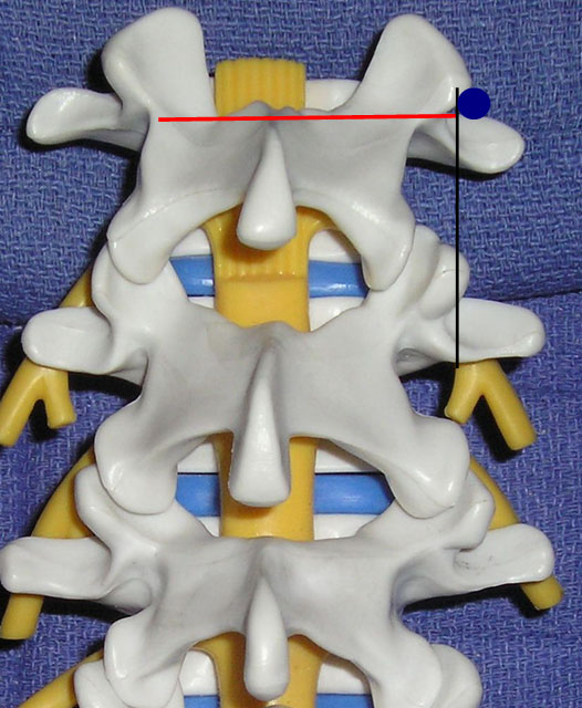
Figure 11. The transducer views utilized for lumbar medial branch blocks: cross axis (red line) and long axis (black line) views. The blue circle indicates the target point.
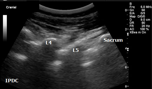
Figure 12. Sonographic long axis view.
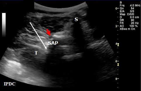
Figure 13. Sonographic cross axis view demonstrating the spinous, transverse and superior articular processes. The white arrow demonstrates the needle pathway for blockade of the lumbar medial branch. Red arrow = Zygapophysial Joint. S = Spinous Process. SA = Superior Articular Process. T = Transverse Process.
Ultrasound Technique for Lumbar Medial Branch Blocks
Greher et al.[34] developed an ultrasound methodology for the lumbar medial branch block. First, the patient is placed in the prone position with a pillow under their abdomen to reduce the lumbar lordosis. The appropriate level of the lumbar spine is identified under the long axis view, and the level to be anesthetized is centered. The transducer is then rotated 90° to the cross axis view. The step-off deformity is seen between the superior articular process and the transverse process. Under real-time ultrasound guidance with an in plane technique, a 22-gauge spinal needle is inserted from lateral to medial (Figure 13). The insertion angle is approximately 45° to 60° to the skin. The needle is directed down to the junction between the superior articular process and the superior border of the transverse process. Once bony contact is reached the transducer is rotated back to the long axis view to confirm that the needle tip is at the cranial edge of the transverse process. Local anesthetic is then injected to anesthetize the targeted medial branch.
Shim et al.[35] also demonstrated the efficacy of the ultrasound lumbar medial branch block technique. In individuals that are obese or with severe degenerative changes, it can be difficult to perform ultrasound-guided lumbar medial branch blocks. Rauch et al.36 demonstrated only a 62% success rate when performing medial branch blocks in individuals with body mass indexes greater than 30 kg/m2. Galiano et al.[37-38] studied the feasibility of ultrasound guided lumbar facet joint injections.
Lumbar Spinal Canal
The anatomy of the lumbar spinal canal can also be assessed with ultrasound. Ultrasound visualization has been utilized in the fields of regional anesthesia[39-41] and emergency medicine[42-44] to assist in lumbar puncture and epidural placement. Typically, ultrasound is used to calculate depth from the skin to the epidural space, to estimate needle insertion angle, and to identify abnormal anatomy within the spinal canal. Some have suggested that identifying abnormal sonoanatomy of the ligamentum flavum in specific individuals may reduce the risk of unintentional complications such as dural puncture.45 Recently, a real-time ultrasound guidance paramedian epidural access approach with loss-of-resistance technique has been developed.[46]
Currently in the field of chronic pain management, ultrasound visualization is not adequate as a sole technique for visualization for interlaminar or transforaminal epidural injections.[1] Secondary to bony artifact and depth constraints, structures within the neural foramen cannot be adequately visualized. In addition, ultrasound does not allow for visualization of injected contrast agent in the epidural space. Digital subtraction fluoroscopy, which is helpful to assist in the avoidance of injecting into critical vascular structures, cannot be utilized. At this point in time, ultrasound use and the visualization of the sonoanatomy of lumbar spine can be viewed as a technique that may be useful in combination with fluoroscopy to provide detail on soft tissue structures in the designated needle path. For example, ultrasound can be used to estimate the depth of the epidural space and to identify abnormal soft tissues in the lumbar spinal region. Ultrasound measured depths of the dura mater and the ligamentum flavum have been found to strongly correlate with the final needle depth.[44] This technology could also be used in individuals with high degrees of stenosis to measure canal diameters prior to progressing forward with the fluoroscopic technique. A prior understanding of the epidural anatomy may facilitate fluoroscopically guided epidural puncture. Currently, fluoroscopy is the recommended visualization technique for epidural injections in the lumbar spine.
Sonoanatomy
A low-frequency curved array transducer is needed in the lumbar spine region. The 2 views used to visualize the spinal canal and its associated landmarks include the paramedian longitudinal (Figure 14) and transverse (axial) windows (Figure 15). A paramedian longitudinal (sagittal) view is the best window for sagittal scanning that minimizes the acoustic artifact shadowing associated with bony structures.[40][43] The appropriate interspace can be identified in the sagittal view based on counting from the landmark of the sacrum.
In the transverse approach the transducer is placed perpendicular to the long axis of the spine. The window is identified in which shadow of the spinous processes is minimal. Structures that can be visualized with ultrasound include the ligamentum flavum/posterior dura complex, spinous processes, transverse processes, superior articular processes, facet joints, and the posterior border of the vertebral body. In certain cases it is not always possible to distinguish the ligamentum flavum from the posterior dura and the anterior dura from the posterior longitudinal ligament and the vertebral body. Ultrasound has also been utilized as an adjuvant tool in the performance of caudal epidurals (Figure 16).
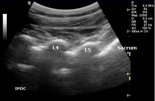
Figure 14. Paramedian oblique longitudinal (sagittal) sonogram of the lumbar spine.
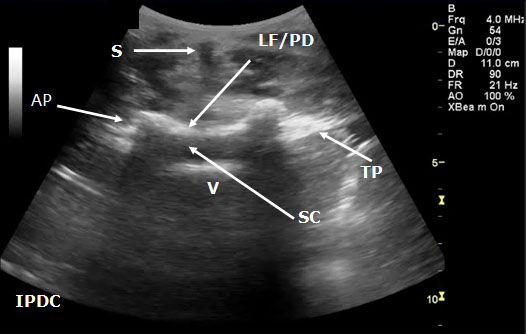
Figure 15. Transverse sonogram of the lumbar interspace. At times it may be difficult to distinguish the ligamentum flavum from the posterior dura. LF/PD = Ligamentum Flavum/Posterior Dura Complex. SC = Spinal Canal. V = Vertebral Body. S = Shadow of the Spinous Process. T= Transverse Process. AP = Articular Process.
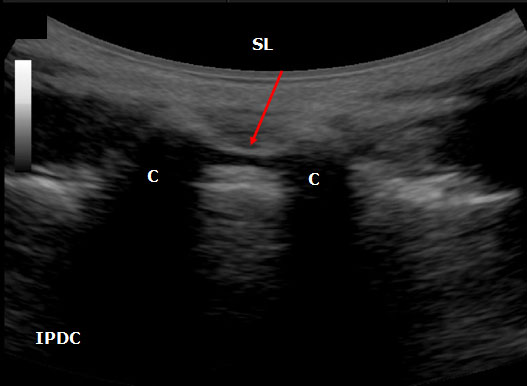
Figure 16. An ultrasound image of the sacral hiatus between the sacral cornuae (C) The sacral hiatus is covered by sacrococcygeal ligament (SL) and its depth is defined the base of the sacrum.
Summary
Ultrasound guidance for chronic pain axial procedures is rapidly evolving. An in-depth understanding of anatomy is important to enable correct identification of sonographically visualized structures. In addition to the above techniques, ultrasound has been utilized for cervical[47] and thoracic epidural and sacroiliac joint injections.[48-50] Additional information on the use of ultrasound for axial structures can be found in the Ultrasonography in Pain Medicine - Special Interest Group Section. Ultrasound has certain visualization advantages and limitations compared to fluoroscopy. In some cases ultrasound guidance for certain procedures may become a preferred technique in the future. In other instances ultrasound guidance may be viewed as an adjunct (e.g. pre-intervention scan) to assist fluoroscopically guided procedures. Future studies are needed on the safety and efficacy of ultrasound guided techniques for axial procedures with direct comparison to fluoroscopy guided techniques.
Acknowledgments
I would like to thank Michelle Smith, RDMS, and the Department of Radiology at Ohio Valley General Hospital for their assistance.
References
- Gofeld M. Ultrasonography in pain medicine: a critical review. Pain Pract 2008;8:226-240
- Schmidt WA, Backhaus M. What the practising rheumatologist needs to know about the technical fundamentals of ultrasonography. Best Pract Res Clin Rheumatol 2008;22:981-999
- Bogduk N. The clinical anatomy of the cervical dorsal rami. Spine 1982;7:319-330
- Lord SM, McDonald GJ, Bogduk N. Percutaneous Radiofrequency Neurotomy of the Cervical Medial Branches: A Validated Treatment for Cervical Zygapophysial Joint Pain. Neurosurgery Quarterly 1998;8:288-304
- Lee SH, Kang CH, Lee SH, Derby R, Yang SN, Lee JE, et al. Ultrasound-guided radiofrequency neurotomy in cervical spine: sonoanatomic study of a new technique in cadavers. Clin Radiol 2008;63:1205-1212
- Eichenberger U, Greher M, Kapral S, Marhofer P, Wiest R, Remonda L, et al. Sonographic visualization and ultrasound-guided block of the third occipital nerve: prospective for a new method to diagnose C2-C3 zygapophysial joint pain. Anesthesiology 2006;104:303-308
- Siegenthaler A, Narouze S, Eichenberger U. Ultrasound-guided third occipital nerve and cervical medial branch nerve blocks. Techniques in Regional Anesthesia and Pain Management 2009;13:128-132
- Galiano K, Obwegeser AA, Bale R, Harlander C, Schatzer R, Schocke M, et al. Ultrasound-guided and CT-navigation-assisted periradicular and facet joint injections in the lumbar and cervical spine: a new teaching tool to recognize the sonoanatomic pattern. Reg Anesth Pain Med 2007;32:254-257
- Galiano K, Obwegeser AA, Bodner G, Freund MC, Gruber H, Maurer H, et al. Ultrasound-guided facet joint injections in the middle to lower cervical spine: a CT-controlled sonoanatomic study. Clin J Pain 2006;22:538-543
- Bruneau M, Cornelius JF, Marneffe V, Triffaux M, George B. Anatomical variations of the V2 segment of the vertebral artery. Neurosurgery 2006;59(Suppl 1):20-24
- Narouze S. Sonoanatomy of the cervical spinal nerve roots: implications for brachial plexus block. Reg Anesth Pain Med 2009;34:616
- Janik JE, Hoeft MA, Ajar AH, Alsofrom GF, Borrello MT, Rathmell JP. Variable osteology of the sixth cervical vertebra in relation to stellate ganglion block. Reg Anesth Pain Med 2008;33:102-108
- Martinoli C, Bianchi S, Santacroce E, Pugliese F, Graif M, Derchi LE. Brachial plexus sonography: a technique for assessing the root level. Am J Roentgenol 2002;179:699-702
- Huntoon MA. Anatomy of the cervical intervertebral foramina: vulnerable arteries and ischemic neurologic injuries after transforaminal epidural injections. Pain 2005;117:104-111
- Huntoon MA. The Vertebral Artery is Unlikely to be the Sole Source of Vascular Complications Occurring during Stellate Ganglion Block. Pain Pract 2009;1-6
- Hoeft MA, Rathmell JP, Monsey RD, Fonda BJ. Cervical transforaminal injection and the radicular artery: variation in anatomical location within the cervical intervertebral foramina. Reg Anesth Pain Med 2006;31:270-274
- Narouze SN, Vydyanathan A, Kapural L, Sessler DI, Mekhail N. Ultrasound-guided cervical selective nerve root block: a fluoroscopy-controlled feasibility study. Reg Anesth Pain Med 2009;34:343-348
- Matula C, Trattnig S, Tschabitscher M, Day JD, Koos WT. The course of the prevertebral segment of the vertebral artery: anatomy and clinical significance. Surg Neurol 1997;48:125-131
- Gofeld M, Bhatia A. Alleviation of Pancoast's tumor pain by ultrasound-guided percutaneous ablation of cervical nerve roots. Pain Pract 2008;8:314-319.
- Scanlon GC, Moeller-Bertram T, Romanowsky SM, Wallace MS. Cervical transforaminal epidural steroid injections: more dangerous than we think? Spine 2007;32:1249-1256
- Provenzano DA, Fanciullo G. Cervical transforaminal epidural steroid injections: should we be performing them? Reg Anesth Pain Med 2007;32:168
- Van Zundert J, Huntoon M, Patijn J, Lataster A, Mekhail N, van Kleef M. 4. Cervical radicular pain. Pain Pract 2009;10:1-17
- Van Zundert J, Huntoon MA, van Kleef M. Complications of transforaminal cervical epidural steroid injections. Spine 2009;34:2477
- Bogduk N. Clinical Anatomy of the Lumbar Spine and Sacrum. Fourth edition ed.: Elsevier Churchill Livingston; 2005
- Taylor JR, Twomey LT. Age changes in lumbar zygapophyseal joints. Observations on structure and function. Spine 1986;11:739-745
- Schmidt H, Heuer F, Wilke HJ. Interaction between finite helical axes and facet joint forces under combined loading. Spine 2008;33:2741-2748
- Lau P, Mercer S, Govind J, Bogduk N. The surgical anatomy of lumbar medial branch neurotomy (facet denervation). Pain Med 2004;5:289-298
- Bogduk N. The lumbar mamillo--accessory ligament. Its anatomical and neurosurgical significance. Spine 1981;6:162-167.
- Bogduk N. The innervation of the lumbar spine. Spine 1983;8:286-293
- Schwarzer AC, Aprill CN, Derby R, Fortin J, Kine G, Bogduk N. The prevalence and clinical features of internal disc disruption in patients with chronic low back pain. Spine 1995;20:1878-1883
- Schwarzer AC, Wang SC, O'Driscoll D, Harrington T, Bogduk N, Laurent R. The ability of computed tomography to identify a painful zygapophysial joint in patients with chronic low back pain. Spine 1995;20:907-912
- Chou R, Loeser JD, Owens DK, Rosenquist RW, Atlas SJ, Baisden J, et al. Interventional therapies, surgery, and interdisciplinary rehabilitation for low back pain: an evidence-based clinical practice guideline from the American Pain Society. Spine 2009;34:1066-1077
- Bogduk N. Evidence-informed management of chronic low back pain with facet injections and radiofrequency neurotomy. Spine J 2008;8:56-64
- Greher M, Scharbert G, Kamolz LP, Beck H, Gustorff B, Kirchmair L, et al. Ultrasound-guided lumbar facet nerve block: a sonoanatomic study of a new methodologic approach. Anesthesiology 2004;100:1242-1248
- Shim JK, Moon JC, Yoon KB, Kim WO, Yoon DM. Ultrasound-guided lumbar medial-branch block: a clinical study with fluoroscopy control. Reg Anesth Pain Med 2006;31:451-454.
- Rauch S, Kasuya Y, Turan A, Neamtu A, Vinayakan A, Sessler DI. Ultrasound-guided lumbar medial branch block in obese patients: a fluoroscopically confirmed clinical feasibility study. Reg Anesth Pain Med 2009;34:340-342
- Galiano K, Obwegeser AA, Bodner G, Freund M, Maurer H, Kamelger FS, et al. Ultrasound guidance for facet joint injections in the lumbar spine: a computed tomography-controlled feasibility study. Anesth Analg 2005;101:579-83
- Galiano K, Obwegeser AA, Walch C, Schatzer R, Ploner F, Gruber H. Ultrasound-guided versus computed tomography-controlled facet joint injections in the lumbar spine: a prospective randomized clinical trial. Reg Anesth Pain Med 2007;32:317-322
- Grau T, Leipold RW, Conradi R, Martin E, Motsch J. Efficacy of ultrasound imaging in obstetric epidural anesthesia. J Clin Anesth 2002;14:169-175.
- Grau T, Leipold RW, Horter J, Conradi R, Martin EO, Motsch J. Paramedian access to the epidural space: the optimum window for ultrasound imaging. J Clin Anesth 2001;13:213-217
- Grau T, Leipold RW, Horter J, Martin E, Motsch J. Colour Doppler imaging of the interspinous and epidural space. Eur J Anaesthesiol 2001;18:706-712.
- Stiffler KA, Jwayyed S, Wilber ST, Robinson A. The use of ultrasound to identify pertinent landmarks for lumbar puncture. Am J Emerg Med 2007;25:331-334
- Ferre RM, Sweeney TW. Emergency physicians can easily obtain ultrasound images of anatomical landmarks relevant to lumbar puncture. Am J Emerg Med 2007;25:291-296
- Ferre RM, Sweeney TW, Strout TD. Ultrasound identification of landmarks preceding lumbar puncture: a pilot study. Emerg Med J 2009;26:276-277
- Lee Y, Tanaka M, Carvalho JC. Sonoanatomy of the lumbar spine in patients with previous unintentional dural punctures during labor epidurals. Reg Anesth Pain Med 2008;33:266-270
- Karmakar MK, Li X, Ho AM, Kwok WH, Chui PT. Real-time ultrasound-guided paramedian epidural access: evaluation of a novel in-plane technique. Br J Anaesth 2009;102:845-854
- Kim SH, Lee KH, Yoon KB, Park WY, Yoon DM. Sonographic estimation of needle depth for cervical epidural blocks. Anesth Analg 2008;106:1542-7
- Hartung W, Ross CJ, Straub R, Feuerbach S, Scholmerich J, Fleck M, et al. Ultrasound-guided sacroiliac joint injection in patients with established sacroiliitis: precise IA injection verified by MRI scanning does not predict clinical outcome. Rheumatology (Oxford) 2009 December 17:1-4
- Klauser A, De Zordo T, Feuchtner G, Sogner P, Schirmer M, Gruber J, et al. Feasibility of ultrasound-guided sacroiliac joint injection considering sonoanatomic landmarks at two different levels in cadavers and patients. Arthritis Rheum. 2008;59:1618-1624
- Harmon D, O'Sullivan M. Ultrasound-guided sacroiliac joint injection technique. Pain Physician 2008;11:543-547.
Leave a commentOrder by
Newest on top Oldest on top