Ultrasound-Guided Lumbar Central Neuraxial Blockade
Note: This article originally appeared in the ASRA News, Volume 16, Issue 1, pp. 15-20 (February 2016).
Authors
Shayanti Meela Ghosh BSc, MBBS, FRCA
Regional Anesthesia Fellow
Ki Jinn Chin MBBS, MMed, FANZCA, FRCPC
Associate Professor
Department of Anesthesia
Toronto Western Hospital
Toronto, ON, Canada
Introduction
Conventional central neuraxial blockade (CNB) techniques employ the use of bony anatomical landmark palpation together with tactile feedback during needle insertion.
In recent years, a substantial evidence base to support the benefits of an ultrasound- (US-) assisted approach to CNB has emerged. The use of a preprocedural US scan identifies vertebral levels more accurately than palpation of surface anatomical landmarks,[1,2] allows precise identification of the underlying anatomy, and facilitates measurement of depth to the intrathecal or epidural space.[3] Neuraxial US improves the technical performance of CNB by reducing the number of skin punctures, needle redirections, and overall needle passes, when compared to conventional landmark-based techniques.[3,4] Neuraxial US is of particular benefit in patients with altered anatomy including obesity,5,6 degenerative age-related changes, and a history of previous spinal surgery where landmark palpation can be challenging. Reduction in technical difficulty may in turn help minimize patient discomfort and dissatisfaction, inadvertent dural puncture, and other serious complications such as spinal hematoma and neural injury.
Gross anatomy of the lumbar spine
The lumbar spine comprises five vertebrae (L1-L5) which, in contrast to the thoracic spine, have laminae and spinous processes that do not overlap. This gives rise to distinct gaps – the interlaminar and interspinous spaces – through which the vertebral canal can be accessed. The anterior wall of the vertebral canal is formed by the posterior longitudinal ligament and the posterior surface of the vertebral bodies and intervertebral discs. The posterior wall of the vertebral canal is comprised of the laminae and the ligamentum flavum. It is important to be familiar with the bony contours of the posterior surfaces of the lumbar spine as these give rise to characteristic patterns on US (Figure 1). In particular, it should be noted that the laminae slope in a cephalo-anterior direction and that the transverse processes and articular processes lie in approximately the same transverse place as the interlaminar space.
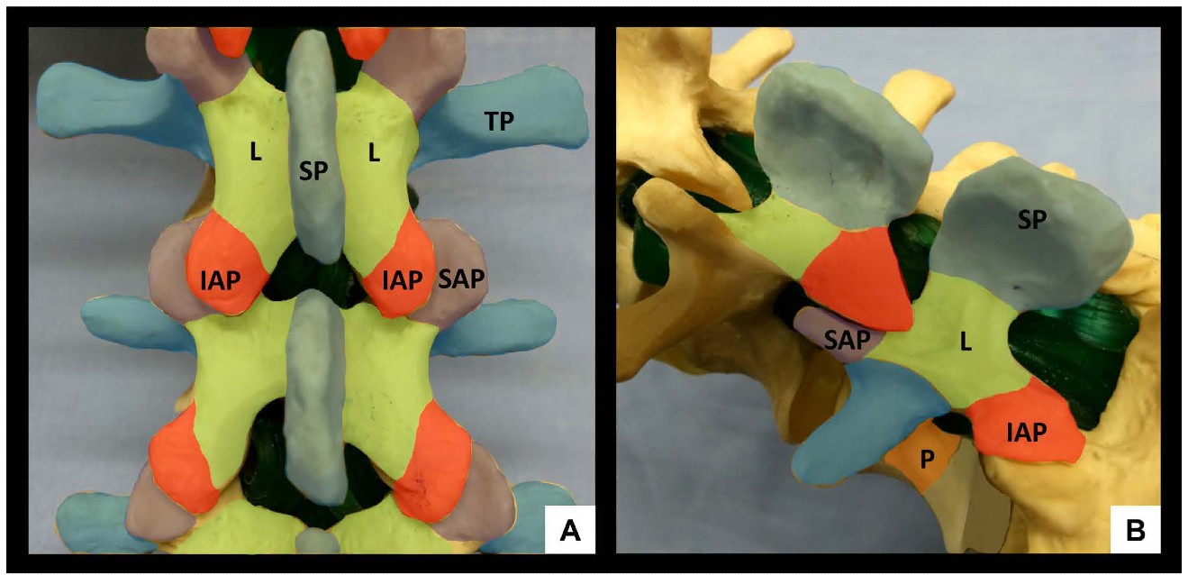 Figure 1: Bony anatomy of the lumbar spine, posterior view (A) and oblique view (B). SP = spinous process, IAP = inferior articular process, SAP = superior articular process, L = lamina, TP = transverse process, P = pedicle
Ultrasonographic views for neuraxial blockade
The primary objectives of neuraxial US are to (1) identify the bony landmarks of the lumbar spine by the characteristic acoustic dropout shadows that they cast, and (2) identify the soft-tissue “windows” of the interspinous and interlaminar spaces which permit sound wave and needle entry into the vertebral canal of sound waves.
General preparation for scanning
The patient is placed in the sitting or lateral decubitus position with the back arched to ‘open’ the interspinous and interlaminar spaces and enlarge the acoustic window. Standard palpation of surface anatomical landmarks should be performed prior to scanning to attempt identification of the L3-4 level and midline. We recommend the use of a curved, low-frequency (2-5 MHz) probe to provide a broad field of view and enhanced beam penetration, both of which aid identification of anatomy.
Systematic approach to scanning, skin marking, and needle insertion
US-assisted midline approach[7]
For the US-assisted midline approach, the most important views in clinical practice are the parasagittal oblique (PSO) interlaminar view and the transverse interlaminar view. Both allow visualization of the neuraxial structures through acoustic windows and can therefore be used to identify and mark appropriate intervertebral spaces as described below.
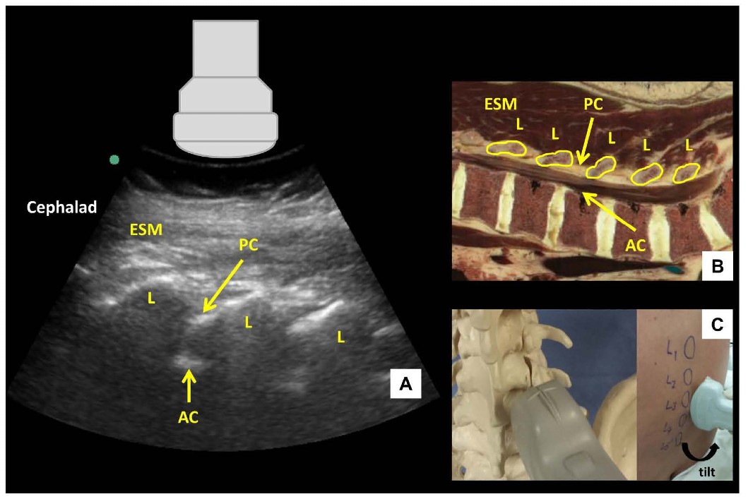
Figure 2: Parasagittal oblique view of the lumbar spine (A) with corresponding anatomical section (B) and ultrasound probe orientation (C). ESM = erector spinae muscle, L = lamina, PC = posterior complex, AC = anterior complex.
The US probe is placed in a parasagittal orientation approximately 3-4 cm lateral to the midline over the lower lumbar spine and slightly cephalad to the sacrum with a slight tilt to direct the US beam toward the midline in an oblique plane. This results in a sawtooth-like pattern characterizing the parasagittal oblique (PSO) interlaminar view (Figure 2). The “teeth” and the intervening gaps correspond to the downsloping laminae and interlaminar spaces respectively. The US beam penetrates the following structures within the interlaminar space (from superficial to deep): ligamentum flavum, epidural space, and posterior dura (collectively referred to as the posterior complex); the intrathecal space; anterior dura, posterior longitudinal ligament and posterior border of the vertebral body (collectively referred to as the anterior complex). The individual components of the anterior and posterior complexes are often not distinguishable in practice.
Once the PSO interlaminar view has been obtained, the probe is slid in a caudad direction until the elongated horizontal hyperechoic line of the sacrum is visualized. This is an important ultrasonographic landmark as the cephalad edge of the sacrum represents the S1 vertebral body and the L5-S1 interspace can therefore be identified. Starting at this point, each interspace is centered on the US screen and a corresponding skin mark is made at the midpoint of the long edge of the probe to indicate its location and identity. If the probe is initially placed too laterally, or insufficiently angled towards the midline, a hump-like pattern of shadowing, instead of the sawtooth-like pattern, will be seen. This pattern of continuous hump-like shadows is formed by the overlapping superior and inferior articular processes characterizing the parasagittal articular process view (Figure 3).
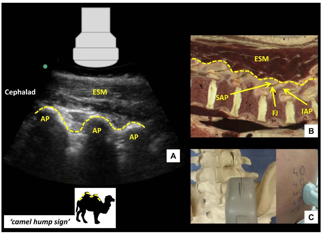
Figure 3: Parasagittal articular process view of the lumbar spine (A) with corresponding anatomical section (B) and ultrasound probe orientation (C). ESM = erector spinae muscle, AP = articular process, SAP = superior articular process, IAP = inferior articular process, FJ = facet joint. Dotted lines in (A) and (B) highlight the contour of the articular processes, resembling a series of camel humps - ‘camel hump sign.’
If the probe is slid even more laterally, the parasagittal transverse process view is obtained (Figure 4). In this view, the transverse processes are visualized as finger-like acoustic shadows, separated by the psoas major muscle. The erector spinae muscle lies superficial (posterior) to the transverse processes.
After the desired interspace has been identified and marked using the PSO interlaminar view, the probe is then turned 90 degrees to obtain the transverse interlaminar view and the midline is centered on the screen (Figure 5). The probe may need to be tilted cranially in the horizontal plane to compensate for spinous process angulation. The interspinous ligament appears as a hypoechoic midline stripe. The intrathecal space can be visualized as a hypoechoic area bounded by the anterior and posterior complexes respectively. The latter are visualized as a set of parallel hyperechoic lines.
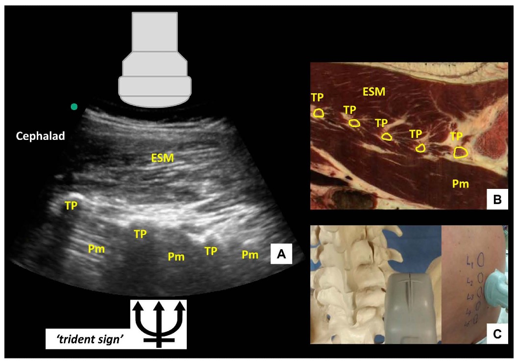 Figure 4: Parasagittal transverse process view of the lumbar spine (A) with corresponding anatomical section (B) (virtual slice extraction from visiblehuman.epfl.ch) and ultrasound probe orientation (C). ESM = erector spinae muscle, TP = transverse process, Pm = psoas muscle. The appearance of the finger-like acoustic shadows produced by the transverse processes is also called the ‘trident sign.
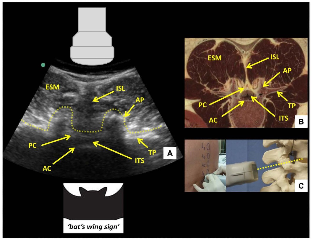 Figure 5: Transverse interlaminar view of the lumbar spine (A) with corresponding anatomical section (B) 4 and ultrasound probe orientation (C). ESM = erector spinae muscle, PC = posterior complex, AC = anterior complex, ITS = intrathecal space, ISL = interspinous ligament, AP = articular process, TP = transverse process. Dotted line in (A) outlines the contour of the ultrasonographic structures giving rise to the ‘bat’s wing sign’. Dotted line in (C) represents the direction of the ultrasound beam.respectively. The latter are visualized as a set of parallel hyperechoic lines.
Skin marks are made at the midpoint of the short and long probe edges, and the needle insertion point for a midline approach lies at the intersection of these two marks. Needle insertion depth can be estimated by measuring the distance from skin to posterior complex. When the probe is moved too cephalad or caudad and lies directly over a spinous process, the tip of the spinous process is seen as a superficial hyperechoic “cap” over an elongated dense acoustic shadow which is referred to as the transverse spinous process view (Figure 6). In this view, the brightly hyperechoic laminae of the vertebral body are visualized at the anterior (deep) border of the erector spinae muscle, which can be seen lateral to the spinous process.
Insertion of the needle occurs at the marked site in the midline with the same cranial angulation (in the horizontal plane) as that used with the ultrasound probe. Minor redirection may occasionally be necessary, and should be made in small increments and guided by tactile feedback. Entry into the epidural and intrathecal space is signaled as usual by loss-of-resistance or cerebrospinal fluid backflow respectively.
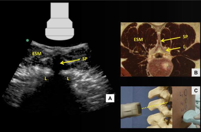 Figure 6: Transverse spinous process view of the lumbar spine (A) with corresponding anatomical section (B) 4 and ultrasound probe orientation (C). ESM = erector spinae muscle, L = lamina, SP = spinous process. Dotted line in (C) represents the direction of the ultrasound beam
US-assisted paramedian approach [8]
A US-assisted paramedian approach may be used as an alternative technique for US-assisted CNB. This may be useful in patients with narrow interspinous and interlaminar spaces due to disease or suboptimal patient positioning, or where the posterior and anterior complexes cannot be visualized. In contrast to the US-assisted midline approach that involves identification of neuraxial structures such as the posterior and anterior complexes, the key landmarks for the US-assisted paramedian approach are merely the neuraxial midline and the spinous processes.
The transverse spinous process view is obtained and the shadow created by the spinous process is centered in the middle of the screen. Skin markings are made at the midpoint of the long edge of the probe (corresponding to the neuraxial midline) and at the midpoint of the probe’s short edge (corresponding to the spinous process in the transverse plane). These markings are made for two consecutive spinous processes.
The needle insertion site is 1 cm lateral to the midline and 1 cm above the line of the lower spinous process. The needle is inserted at a slight (5°-10°) medial and cranial angulation. If lamina is contacted, the needle is redirected cranially in small increments to walk off into the interlaminar space.
Limitations of US-assisted CNB
Neuraxial ultrasound has some limitations. In some elderly and obese patients, clear visualization of deeper structures in the vertebral canal, such as anterior and posterior complexes, can be problematic. In very thin patients, prominence of spinous processes can lead to poor skin-probe contact and poor-quality images. Operator-dependent factors may additionally contribute to lack of success with US-assisted CNB. In general, there can be a significant learning curve to acquisition and recognition of YS images. Learning studies suggest that at least 30-40 procedures are required to achieve competency.[9] More specifically, inaccuracy of skin marking is an inherent problem since tissue distortion (particularly in elderly patients with loose, mobile skin) and compression by the US probe is inevitable. The latter also may contribute to minor discrepancies when measuring required needle insertion depth.
Conclusion
US-assisted CNB does not supplant the conventional surface landmark-guided approach, which is simple and effective in the majority of patients. Rather, it is an advanced technique to be used when difficulty is anticipated or encountered, or when increased precision is desired. However, as with all advanced technical skills, neuraxial US should be practiced in straightforward patients until proficiency is attained.
References
- Whitty R, Moore M, Macarthur A. Identification of the lumbar interspinous spaces: palpation versus ultrasound. Anesth Analg. 2008; 106:538-540.
- Duniec L, Nowakowski P, Kosson D, Lazowski T. Anatomical landmarks based assessment of intervertebral space level for lumbar puncture is misleading in more than 30%. Anaesthesiol Intensive Ther. 2013; 45:1-6.
- Perlas A, Chaparro L, Chin KJ. Lumbar Neuraxial Ultrasound for Spinal and Epidural Anesthesia. A systematic Review and Meta-Analysis. Reg Anesth Pain Med. 2015; 40(2): March-April 2015.
- Shaikh F, Brzezinsi J, Alexander S, et al. Ultrasound imaging for lumbar punctures and epidural catheterizations: systematic review and meta-analysis. BMJ. 2013; 346:f1720-1731.
- Chin KJ, Perlas A, Chan V, et al. Ultrasound imaging facilitates spinal anesthesia in adults with difficult surface anatomical landmarks. Anesthesiology. 2011; 115:94-101.
- Sahin T, Balaban O, Sahin L. A randomized controlled comparison of preinsertion ultrasound guidance for spinal anesthesia in pregnancy; outcomes among obese and lean parturients. J Anesth. 2014; 28(3):413-419.
- Chin KJ, Karmakar MK, Peng P. Ultrasonography of the adult thoracic and lumbar spine for central neuraxial blockade. Anesthesiology. 2011; 114:1459-1485.
- Chin KJ, Perlas A, Chan V. The ultrasound-assisted paraspinous approach to lumbar neuraxial blockade: a simplified technique in patients with difficult anatomy. Acta Anaesthesiol Scand. 2015; 59: 668-673.
- Margarido CB, Arzola C, Balki M, et al. Anesthesiologists’ learning curves for ultrasound assessment of the lumbar spine.
Anatomic images: courtesy Prof. R. D. Hersch, Ecole Polytechnique Fédérale de Lausanne (EPFL), site: http://visiblehuman.epfl.ch, with original 3D data from the Visible Human Project, U.S. National Library of Medicine, Bethesda.
Leave a commentOrder by
Newest on top Oldest on top