POCUS Spotlight: Point-of-Care Ultrasound of the Eyes
Cite as: Mehra C, Chakraborty A, Dikshit A. POCUS spotlight: point-of-care ultrasound of the eyes. ASRA Pain Medicine News 2024;49. https://doi.org/10.52211/asra050124.012.
Abstract
Ophthalmic Point-of-Care Ultrasound (POCUS) has found increasing application by anaesthesiologists, emergency physicians, trauma physicians, and intensivists. Ophthalmic POCUS provides a unique non-invasive monitoring modality of intracranial pressure, (ie, optic nerve sheath diameter), which is being used as a diagnostic, therapeutic, and prognostic tool in neurocritical care and anaesthesia. Rapid systematic ultrasound assessment of the eyes in trauma patients can also quickly diagnose globe rupture, retinal detachment, and vitreous haemorrhage. The following article describes some of the commonly used ophthalmic POCUS techniques and their applications.
Introduction
Ultrasound has been used for various measurements in ophthalmology for more than two decades. In contrast, the practice of point-of-care ophthalmic ultrasound by anesthesiologists, intensivists, and emergency physicians is fairly recent. This article describes some common uses of ophthalmic POCUS for non-ophthalmologists.
Optic Nerve Sheath Diameter (ONSD)
Ultrasound (US) aided detection of raised optic nerve sheath diameter has been considered a reliable non-invasive indicator of intracranial hypertension.1,2,3
The intracranial pressure (ICP) is related to mean arterial pressure (MAP) by the equation for cerebral perfusion pressure (CPP).
CPP = MAP - ICP
As the difference between the intracranial pressure and mean arterial pressure decreases, the cerebral perfusion also decreases, which increases the incidence of cerebral ischemia.4 Thus, ICP is a fundamental parameter for monitoring cerebral perfusion.
A rise in hydrostatic pressure in the brain tissues, which can occur with rapid intravenous fluid infusions in major abdominal surgeries, pneumoperitoneum, and steep Trendelenburg position, may lead to an increase in ICP.5
An elevation of ICP secondary to cerebral edema is a major contributor to morbidity and mortality in trauma, neurosurgical patients as well as to acute liver failure.6 Geriatric patients with multiple comorbidities undergoing robotic surgeries with steep Trendelenburg position may face impaired cerebral autoregulation caused by alterations in cerebral homeostasis due to a prolonged duration of surgery.7–9
Invasive methods of ICP monitoring are considered the gold standard for detection of a rise in ICP.4 The practical challenges with invasive methods include the requirement of trained personnel for the catheter insertion, maintenance, and troubleshooting as well as the inherent risks of cerebral trauma and infection. In contrast, a noninvasive US assisted technique is more desirable for routine monitoring, owing to its repeatability, easy availability in the OR and ICUs, and minimal training requirements.10-14 For this reason, ONSD estimation by POCUS has now become an essential part of neurocritical care management.15-19 It can be a valuable surrogate for invasive monitoring for assessment of ICP in patients who present with coagulopathy and raised ICP.6,20
Perioperative ICP monitoring may be beneficial for guiding the administration of targeted therapy (ie, mannitol, hypertonic saline, hyperventilation, and reverse Trendelenburg positioning) to prevent brain herniation and plan for decreasing ventilatory requirements. ONSD assessment has proven to be useful for monitoring high ICP in patients with brain injury, idiopathic intracranial hypertension, and spontaneous intracranial haemorrhage.1,21 Papilledema can also be detected as an optic disc bulge into the retina.
ONSD changes rapidly with an increase in end-tidal CO2 (hypercapnia) and returns to baseline with hyperventilation. In contrast, hypocapnia does not significantly reduce ONSD as it is probably near its minimal diameter at rest.22
With the above-mentioned advantages of being non-invasive, safe, and inexpensive with a relative ease of learning, there are a few shortcomings of US measurement of ONSD as a surrogate to ICP.
- Acute changes in blood pressures (> 10% of initial values) at the time of assessment can lead to blood pressure induced changes in ONSD.23,24
- ONSD can’t be measured in ophthalmic injuries, such as ruptured globe.
- ONSD offers a poor predictive value of optic nerve damage in patients with glaucoma.25
Anatomic Correlation
The optic nerve sheath is contiguous with the dura mater, and its contents are contiguous with the subarachnoid space. A rise in the ICP leads to an increase in the optic nerve sheath diameter. Therefore, it can be used as an indirect correlate for ICP assessment.
Cerebrospinal fluid in the subarachnoid space is equitably distributed at around 3 mm behind the globe.
Cerebrospinal fluid in the subarachnoid space is equitably distributed at around 3 mm behind the globe. Thereby, this area is considered to be the region of greatest ultrasound contrast.
An ONSD measurement of up to 5 mm is considered normal. Elevated ICP should be suspected with an ONSD measurement of more than 5 mm (in the presence of clinical features of raised ICP).
For perioperative use, a baseline ONSD should be measured before positioning the patient for surgery.
Procedure for Ocular Ultrasound
- Probe selection and setting:
- A high resolution, 7.5-10 MHz or higher, linear array ultrasound transducer, held with a pencil grip.
- Select the “ophthalmic” preset in the ultrasound machine. In machines without an “ophthalmic” preset, decrease the power output to minimum. Set the ultrasound machine on “small parts” preset.
- Adjust B-mode settings for near-field eye examination (Adherence to current guidelines for orbital insonation is advisable).26
- Probe – eye interface preparation:
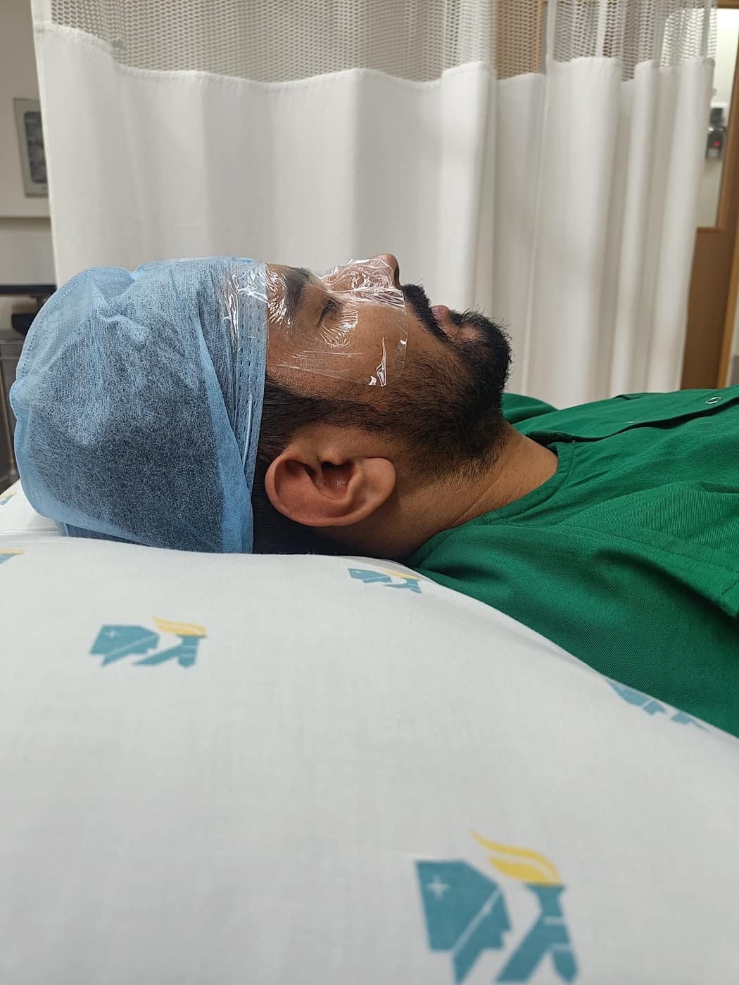
- Cover eyelids with a sterile transparent dressing to prevent contamination or trauma during the scan procedure (Figure 1).
- Apply an adequate amount of water-based gel (ultrasound gel) onto the interface of the transparent dressing and the ultrasound probe.
- Apply very gentle pressure over the eye while keeping your hand on the patient's face to avoid discomfort/trauma to the eye.
- Ultrasound image:
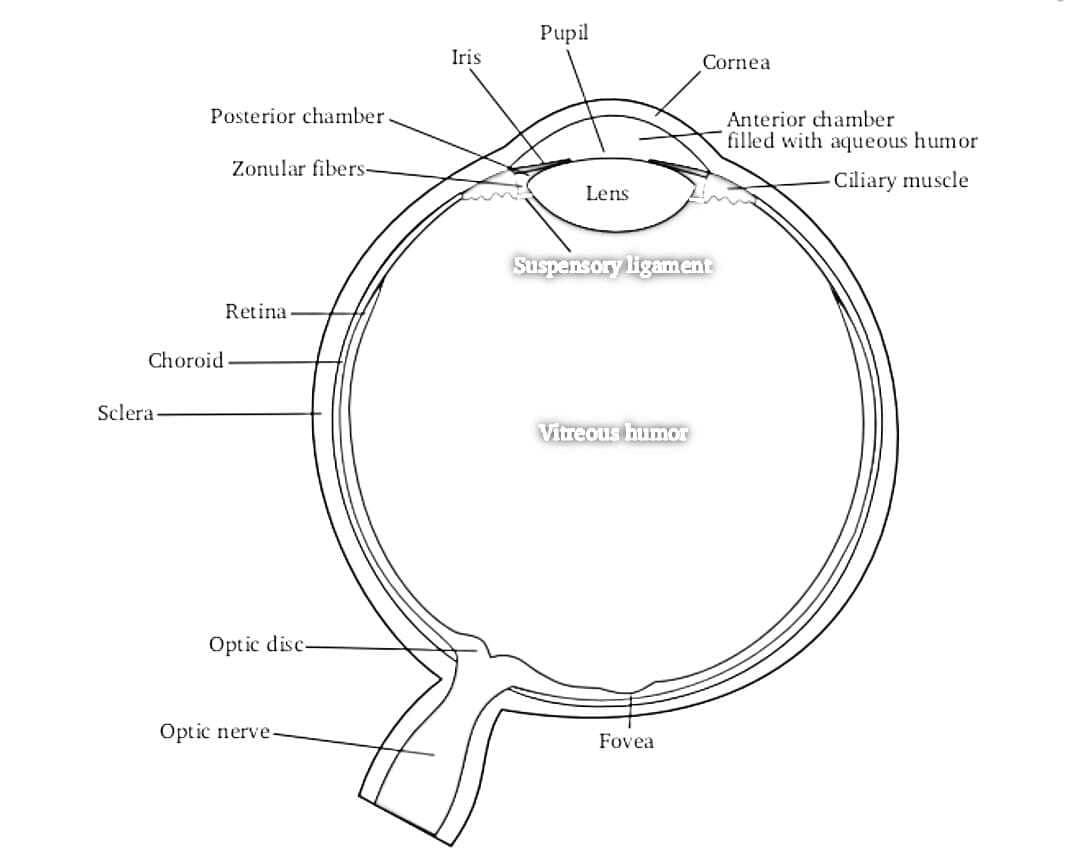
- The eye is scanned to assess normal anatomy and landmarks.
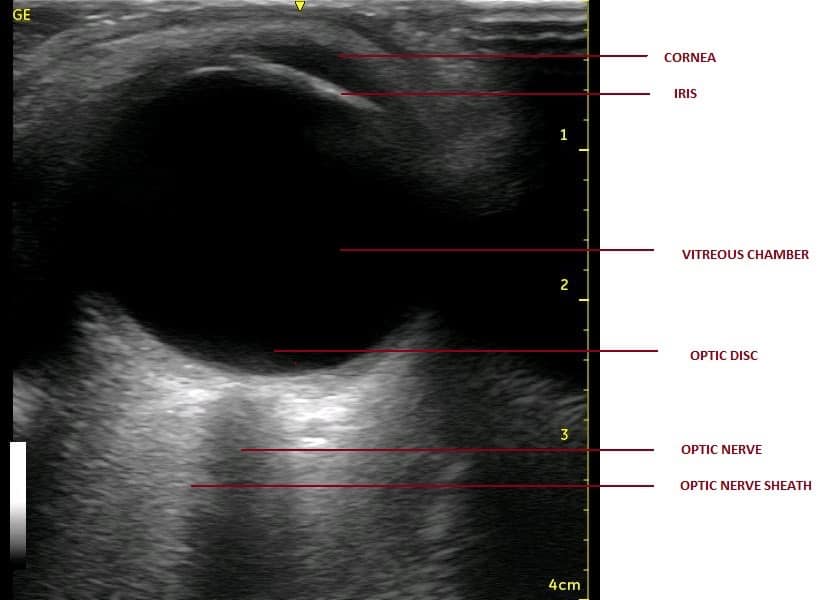
- The following structures are visualised from near to far field (anterior to posterior direction) to gain a proper orientation before proceeding with any measurements (Figures 2 and 3).37
| STRUCTURE | ECHOGENICITY |
| Cornea | Hypoechoic |
| Anterior chamber | Anechoic |
| Lens capsule | Hyperechoic |
| Iris and ciliary body | Hyperechoic |
| Posterior chamber | Anechoic |
| Retina/choroid/sclera (covering layers of eyeball) | Hyperechoic |
| Retro-orbital region (EOM/orbit) | Heterogeneously hyperechoic |
| Optic nerve with its covering sheath | Anechoic linear structure enclosed in hyperechoic sheath (optic nerve sheath) |
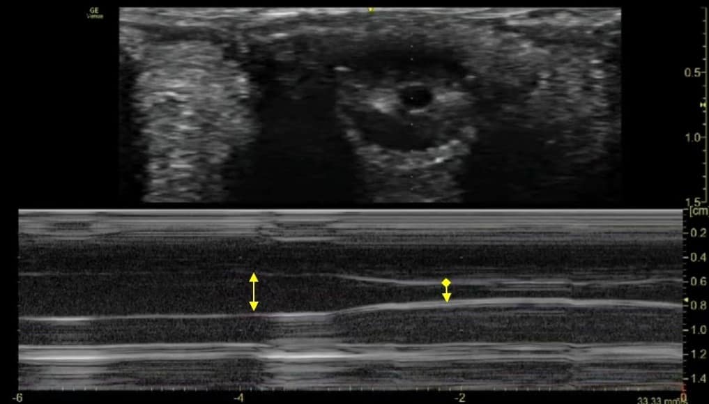
Optic nerve is seen as anechoic (black) linear structure bounded by hyperechoic (bright) lines
- Target depth:
- A point 3 mm posterior to the optic disc is considered the target point. The optic nerve is considered to be most distensible and hence representative of rise in ICP at this point.
- The optic nerve is seen as an anechoic (black) linear structure bounded by hyperechoic (bright) lines, ie, optic nerve sheath at this level (behind the optic disc).
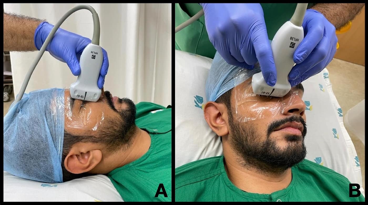
- Scan protocol: Ultrasound examination is carried out at two axes perpendicular to each other.
- Horizontal Scan: Probe is placed in a line joining both canthi, i.e, horizontal axis (Figure 4A).
- Vertical Scan: Probe is placed in a plane perpendicular to first plane, ie, vertical axis (Figure 4B).
- Measurements are taken in both axes, and a mean of ONSD in both transverse and vertical axes is taken as the final measurement representative of ONSD (Figure 5).
Thermal Index and Safety Precautions:
While performing POCUS of the eyes, one must be aware that ultrasound waves are absorbed in the subject tissues, which generate heat. The generation of heat depends on various factors, including the “thermal index” (TI) and the duration of examination. The TI depends on a measure of time-averaged acoustic power output, assumptions of the properties of the tissue being heated, and assumptions about the path of the ultrasound beam.
It is recommended to reduce power settings to a minimum according to the ALARA (as low as reasonably achievable) insonation approach.28 It is suggested to use values less than .23 for the mechanical index and less than 1 for the thermal index.29
The following are recommendations for the safe use of ultrasound examination for ophthalmic examination should be considered:30
- Apply the presets of an examination correctly if they are integrated into the US diagnostic device. Review the factory default presets to verify their suitability.
- Adjust the power to the lowest setting available to produce diagnostic-quality images.
- Monitor the mechanical index (MI) and TI. It is prudent to know the recommended upper limit of MI and TI and related duration limitations for the type of examination to be performed.
- Move/remove the transducer when stationary imaging is not needed to reduce the time spent on a particular anatomical structure.
- Minimize the overall scan time to obtain the required diagnostic information.
The British Medical Ultrasound Society published a guideline for the safe use of diagnostic medical ultrasound in 2009, which puts the eyes in the same category of “sensitive” tissues as the human embryo and does not permit the usage of TI >1.0. 21
The cornea and the lens of the eye are avascular structures and possess a large amount of collagen. This makes them more prone to the absorption of ultrasound energy. Hence, they are more likely to develop an increased temperature during prolonged ultrasound exposure.
Lizzi et al.31 have demonstrated permanent lesions of the retina, choroid, and sclera when produced with the use of focused ultrasound at 9.8 MHz in a rabbit model. The authors also reported transient chemosis, conjunctival injection, and occasional hemorrhage. The different degrees of lesions depended on the duration and intensity of exposure. Corneal endothelial damage is a known risk of ultrasound phacoemulsification.32
Many US machines have an “ophthalmic” preset, which makes the work easier and safer by automatically adjusting MI and TI within safety limits for ophthalmic ultrasound examination. In absence of such features, the power output setting must be set to a minimal level before commencing examination. One should also remember that the color doppler and the spectral doppler modes of ultrasound use more power output, hence have a higher TI. The duration of ultrasound assessment should be limited in order to decrease the exposure time. It is important to make all the associated arrangements before initiating ultrasound assessment of the eyes to keep the session brief.
Conclusion Regarding ONSD
- The technique of ONSD measurement by ultrasound of the eye is an established screening tool for predicting raised ICP in trauma patients.
- The cut-off values of ONSD for predicting a raised ICP vary from .48 to .59 cm in different studies. Studies that compare ONSD with invasive ICP monitoring correlate an invasive ICP of > 20 mm Hg with an ONSD of 5.7 - 6.0 mm.
A value more than 5.82 mm of ONSD confirms raised ICP with a sensitivity of 90%, a specificity of 92% and a negative predictive value of 92%. A value less than 5.3 mm of ONSD rules out raised ICP with 100% sensitivity and negative predictive value.33 However, the accuracy of measurement of ONSD may vary with probe orientation and experience of the ultrasonographer. So, a mean of ONSD values is clinically more relevant.
- A serial change in ONSD is more important than an absolute single value, though this must be validated. Bender et al. have termed changes in serial ONSD measurements as stable or unstable ONSD trend.34 The authors considered that the patient had an unstable ONSD trend if the variations (increase or decrease) of average ONSD (left or right) were above 5%.
- ONSD is a non-invasive method of detecting elevated ICP with great sensitivity, even during surgical procedures with rapid reversibility.22,35
- ONSD is more accurate than color doppler indices of the ophthalmic artery (ocular doppler ultrasound) in assessment of elevated ICP.36
- In patients with suspected raised ICP presenting with symptoms like agitation, sedation, confusion, blurring of vision, conjunctival or periorbital oedema, or delayed awakening from anaesthesia, ONSD measurement can guide further management.20
Central Retinal Artery Occlusion (CRAO)
Ultrasound examination of the eye can help to diagnose CRAO in cases of a sudden blurring or loss of vision, eg, after major spine surgery, long duration prone position ventilation in ARDS patients, or intubated patients with COVID-19, etc.
It is observed as a hyper-echoic spot (ditzel) in the center of the optic nerve (retro-bulbar spot sign). This hyper-echogenic spot represents thrombosis of the central retinal artery.37 Retinal blood flow occlusion can be confirmed with use of color doppler (Figure 6 and Video 1), the accuracy of which itself depends upon the angle of insonation of the ultrasound beam.
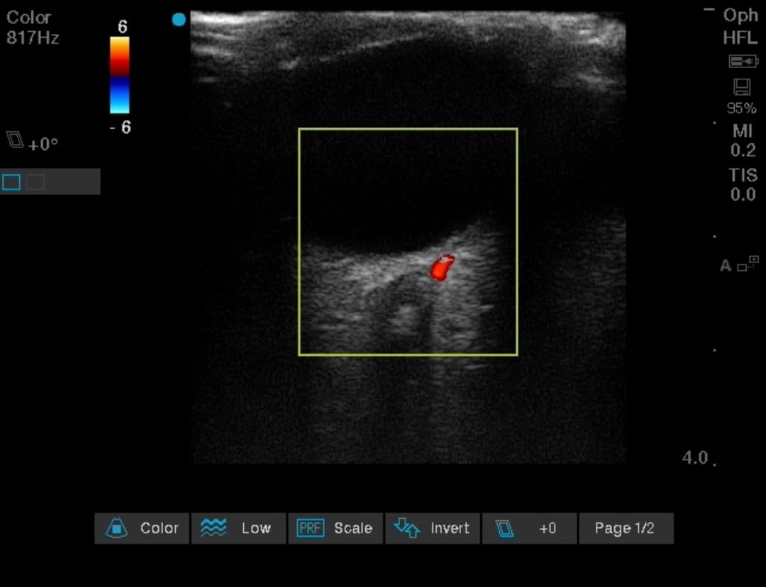
A false positive assessment can be made in case of optic nerve drusen, which is a calcific material deposit in the head of the optic nerve/retina and presents clinically as blurring or loss of vision. Ocular ultrasound provides high specificity but low sensitivity to confirm diagnosis of CRAO.
Vitreous Versus Retinal Detachment
Ultrasound examination of the eye can help to diagnose and differentiate between retinal and vitreous detachment in emergency scenarios.38
- Retinal detachment: Appears as a bright, continuous, smooth, and somewhat folded membrane within the vitreous, and freely moving on real-time imaging and is seen coming out of the optic nerve.
- Vitreous detachment: Posterior vitreous detachment is seen as a freely mobile hyperechoic membrane that swirls away from the optic disc with movement of the eye.
The mobile membrane is seen to cross the midline with the optic disc representing the midline, ie, the line is seen crossing over the optic nerve and not attached to it.
Pupillary Assessment with POCUS (Direct and Consensual Light Reflex, Pupillary Diameter)
Ultrasound assisted pupillary examination (ie, bilateral evaluation of pupil size, shape, symmetry, and reactivity) is a simple, widely available non-invasive method for neurologic examination in a critically ill patient. External ocular injuries may make it challenging to assess the pupil for examination.
The consensual pupillary reflex assesses an abnormality in the integrity of the retina, optic nerve, portion of the midbrain, and the oculomotor nerve. This can indirectly correlate with a timely diagnosis of retinal integrity, intracranial or an extracranial haemorrhage, necessitating an appropriate treatment.39
Assessment of the pupil with ultrasound helps the clinician to evaluate the pupillary light reflex (PLR). Additionally, it allows recording of additional parameters, such as the rate of constriction, latency time, and dilatation time of the pupil.40
The Brain Trauma Foundation’s guidelines for the management of severe traumatic brain injury acknowledge the evaluation of pupillary size and reactivity to light as a source for early prognostic signs of neurologic pathology.41
There is considerable intra- and inter-observer variability due to inconsistency on several factors, such as illumination of the patient’s room, examiner’s visual acuity and experience, and intensity and technique of light stimuli while using the conventional, visual pupillary assessment.42
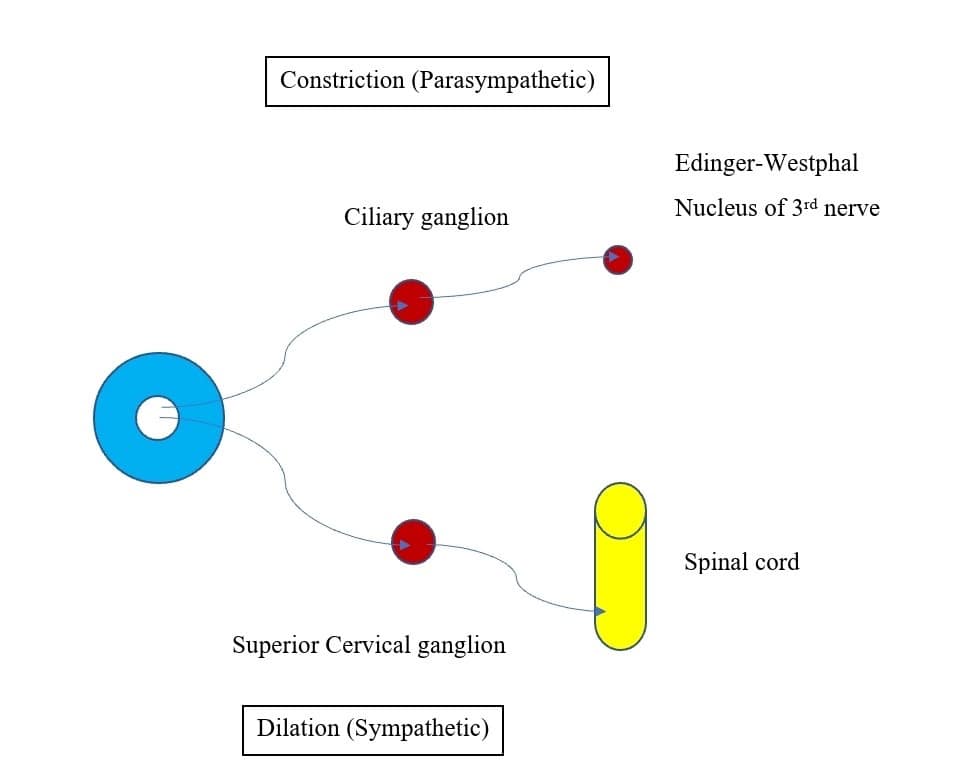
Pupillary constriction is an interaction between the sympathetic and parasympathetic nervous systems (Figure 7). Parasympathetic innervation leads to pupillary constriction via the sphincter pupillae muscle. Sympathetic innervation leads to pupillary dilation via the dilator pupillae, a group of muscles in the peripheral two-thirds of the iris.
Direct and Consensual Light Reflex
Ultrasound examination of the eye can be used to assess consensual light reflex in patients who can’t open the ipsilateral eye for pupillary examination because of reasons like trauma, swollen eyelid, etc.
Probe selection and preparation is the same as for ONSD. Patient positioning can be sitting, upright, semi-upright, or supine. For standardization, a penlight with a luminous emittance of 70,000 Lux and a stimulus time of 2 seconds should be used to ensure constant wavelength, intensity, and duration of the light stimulus as the PLR is dependent on these properties of light.29
- Ultrasound views:
The iris can be visualized in either of the two views:
- Transverse/sagittal view:
- The probe is placed transverse or para-sagittal over the eyeball with the ultrasound beam directed towards the back of the eye. The iris can be seen as a linear structure extending from the peripheral globe towards the lens. It can be observed as a smiling face with eyes representing iris and smiling lips representing the lens (Figure 8A).
- Coronal view:
- Inferior orbital probe placement approach (trans-palpebral tangential view):
The patient is instructed to look at a fixed object on the ceiling so that a stable gaze upwards is fixated. The ultrasound probe is placed over the lower part of the globe (over the zygomatic bone) with the ultrasound beam insonating cranially, taking advantage of Bell’s phenomenon.43 Initially, an oblique section of the globe can be visualised. With further tilting of the probe, a gradual transition of the scanning plane is seen from the initial transverse to a near coronal plane (Figure 8B). Thereafter, the plane of the iris is aligned with the scanning plane. The iris with the pupil can now be identified in coronal orientation (Figure 9A).40
- Superior orbital probe placement approach:
The pupillary light reflex can also be performed from a superior approach to the eye, by placing the ultrasound probe transversely on the superior margin of the orbit. The probe is tilted upwards until the pupil and iris are visualized in a coronal view, as a discrete anechoic circle surrounded by the iris in the near field of the image. Using this approach, the patient is instead instructed to look downward toward his or her feet (Figure 9B).40
- Inferior orbital probe placement approach (trans-palpebral tangential view):
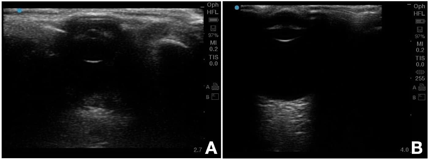
Figure 8 A and B. Coronal and sagittal view of the iris (pupil). 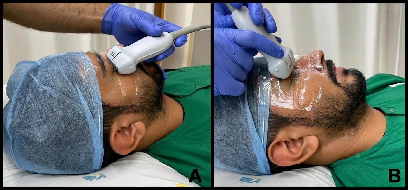
Figure 9. (A) superior orbital and (B) inferior orbital probe placement for eliciting pupillary light reflex. - Transverse/sagittal view:
- Assessment of Direct and Consensual PLR:
- Observe the iris as an anechoic opening within the pupil.
- A direct PLR can be elicited by directing a pen-light stimulus on to the ipsilateral closed eye.
- This is followed by a light stimulus on to the opposite eye to assess for consensual light reflex.
- Pupillary activity along with maximum and minimum pupillary diameters can be assessed (Figure 10).
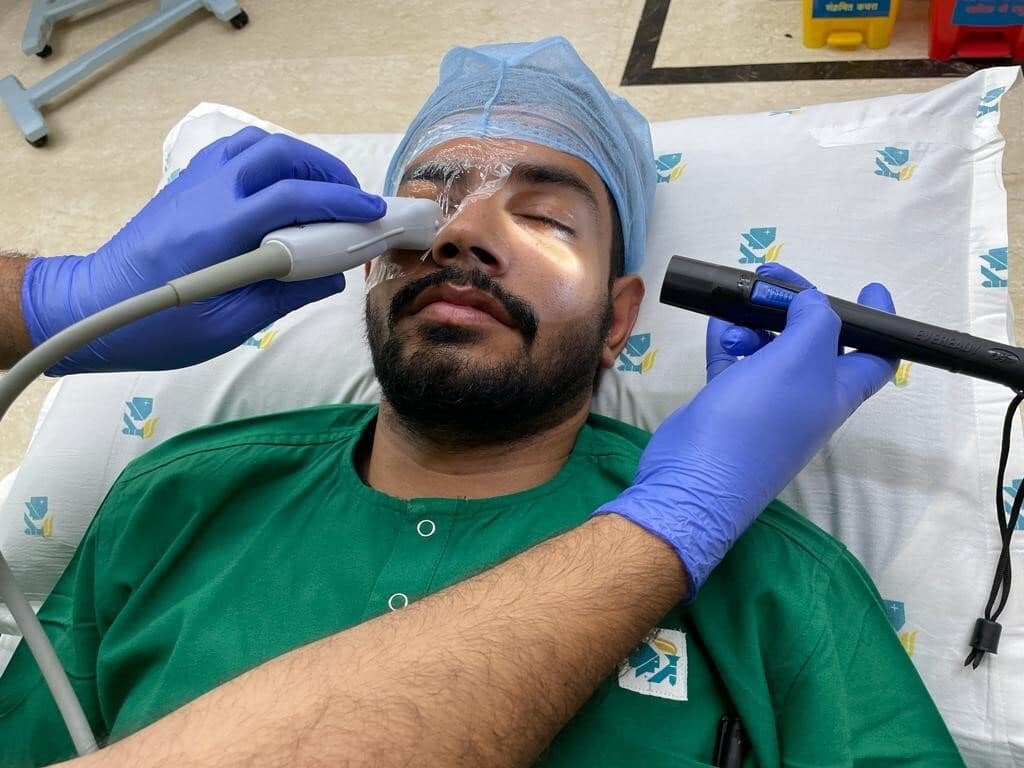
Figure 10. Method to assess consensual light reflex (probe placed over the eye to be examined and pen light shown over the opposite eye). - Scanning modes: The iris can be examined in both B and M modes.
- B mode: Consensual PLR can be recorded as a series of coronal or para-sagittal images of the iris over a period of time (Figure 11 and Video 2).
- M mode: M-mode graphs corresponding to B scans can be acquired to demonstrate the pupillary diameter versus time (Figure 11 and Video 2). This allows analysis of the fine detail of the iris constriction.
The pupil is first displayed in the centre of the screen. A clear M mode display is obtained. The image of the pupil is then recorded while performing direct and consensual PLR using M mode. The frozen M-mode ultrasound images are stored.
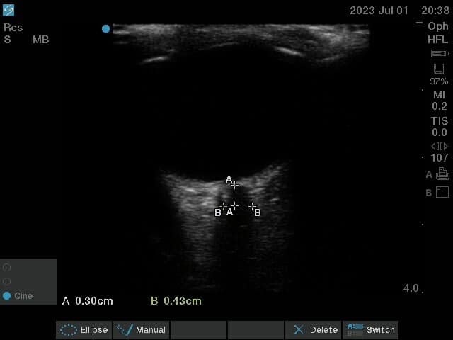
- The maximum and minimum pupillary diameter at rest and at light reflex are marked using the built-in measurement tool in the ultrasonic system.
- The pupillary contraction time (PCT-defined as the time interval between the maximum and minimum PD during the process of light reflex) is calculated using the still images recorded with the ultrasound.
- The sensitivity of the pupillary reflex (brisk, sluggish, absent) can also be assessed.
Assessment of Pupillary Diameter
The pupillary diameter of the individual eye can be assessed and digitally documented at rest as well as during contralateral light stimulus. The extent of pupillary constriction can be calculated as the difference between pupillary diameter at rest and during ipsilateral and contralateral light stimulus.29 Ultrasound examination can help to assess a new onset anisocoria and a variable pupillary response due to a cranial nerve compromise or a life-threatening intra-cranial pathology, prompting an urgent treatment.44,45
A single pupillary diameter assessment is obtained by the use of calliper-based measurement on a frozen image of the ultrasound scan. This may lead to inaccurate results with variation in pupil size. Ultrasound assessment has the advantage of easy repeatability and reproducibility, which averages out any small difference in pupillary diameters.29 On the M-mode strip, the superior-to-inferior diameter of the pupil is represented as a black band across the strip (Figure 11).
Conclusions Regarding Pupillary Assessment
The use of real-time coronal imaging of the pupil and the iris is a reliable and reproducible method for evaluating PLR. The superficial location of the eye, its cystic composition, and the advent of high-frequency ultrasound make sonography ideal for imaging the eye.46,47 PLR assessment with the use of US (direct and consensual) over a traumatised eye helps to assess and target further treatment in neurocritical patients.


References
- Amini A, Kariman H, Arhami Dolatabadi A, et al. Use of the sonographic diameter of optic nerve sheath to estimate intracranial pressure. Am J Emerg Med 2013;31(1):236–39. https://doi.org/1016/j.ajem.2012.06.025
- Lovrencic-Huzjana A, Simicevic DS, Popovic IM, et al. Ultrasonography of the optic nerve sheath in brain death. Perspectives in Medicine2012;1:414–6.
- Messerer M, Berhouma M, Messerer R, et al. Interest of optic nerve sheath diameter ultrasonography in detecting non-invasively raised intracranial pressure. Neurochirurgie2013;59(2):55–9. https://doi.org/10.1016/j.neuchi.2013.02.001
- Wijdicks EFM, Varelas PN, Gronseth GS, et al. Evidence-based guideline update: determining brain death in adults: report of the quality standards subcommittee of the American Academy of Neurology. Neurology2010;74(23):1911–8. https://doi.org/10.1212/WNL.0b013e3181e242a8
- Sahay N, Sharma S, Bhadani UK, et al. Effect of pneumoperitoneum and patient positioning on intracranial pressures during laparoscopy: a prospective comparative study. J Minim Invasive Gynecol 2018;25(1):147-52. https://doi.org/10.1016/j.jmig.2017.07.031
- Dubourg J, Javouhey E, Geeraerts T, et al. Ultrasonography of optic nerve sheath diameter for detection of raised intracranial pressure: a systematic review and metaanalysis. Intensive Care Med2011;37:1059–68. https://doi.org/10.1007/s00134-011-2224-2
- Barr C, Madhuri TK, Prabhu P, et al. Cerebral oedema following robotic surgery: a rare complication. Arch Gynecol Obstet 2014;290(5):1041-4. https://doi.org/10.1007/s00404-014-3355-9
- Schramm P, Treiber AH, Berres M, et al. Time course of cerebrovascular autoregulation during extreme Trendelenburg position for robotic-assisted prostatic surgery. Anaesthesia 2014;69(1):58–63. https://doi.org/10.1111/anae.12477
- Tourinho-Barbosa RR, Tobias-Machado M, Castro-Alfaro A, et al. Complications in robotic urological surgeries and how to avoid them: a systematic review. Arab J Urol 2017;16(3):285-92. https://doi.org/10.1016/j.aju.2017.11.005
- Talving P, Karamanos E, Teixeira PG, et al. Intracranial pressure monitoring in severe head injury: compliance with brain trauma foundation guidelines and effect on outcomes: a prospective study. J Neurosurg2013;119(5):1248–54. https://doi.org/10.3171/2013.7.JNS122255
- Young GB, Shemie SD, Doig CJ, et al. Brief review: the role of ancillary tests in the neurological determination of death. Can J Anaesth 2006;53(6):620–7. https://doi.org/10.1007/BF03021855
- Lustbader D, O'Hara D, Wijdicks EFM, et al. Second brain death examination may negatively affect organ donation. Neurology2011;76(2):119–24. https://doi.org/10.1212/WNL.0b013e3182061b0c
- Vicenzini E, Pro S, Pulitano P, et al. Current practice of brain death determination and use of confirmatory tests in an Italian University hospital: a report of 66 cases. Minerva Anestesiol 2013;79(5):485–91.
- Potgieter DW, Kippin A, Ngu F, et al. Can accurate ultrasonographic measurement of the optic nerve sheath diameter (a non-invasive measure of intracranial pressure) be taught to novice operators in a single training session? Anaesth Intensive Care2011;39(1):95–100. https://doi.org/10.1177/0310057X1103900116
- Shah S, Kimberly H, Marill K, et al. Ultrasound techniques to measure the optic nerve sheath: is a specialized probe necessary? Med Sci Monit2009;15(5):MT63–8.
- Helmke K, Hansen HC. Fundamentals of transorbital sonographic evaluation of optic nerve sheath expansion under intracranial hypertension II. Patient study. Pediatr Radiol 1996;26(10):706–10. https://doi.org/10.1007/BF01383384
- Geeraerts T, Launey Y, Martin L, et al. Ultrasonography of the optic nerve sheath may be useful for detecting raised intracranial pressure after severe brain injury. Intensive Care Med 2007;33(10):1704–11. https://doi.org/10.1007/s00134-007-0797-6
- Geeraerts T, Merceron S, Benhamou D, et al. Non-invasive assessment of intracranial pressure using ocular sonography in neurocritical care patients. Intensive Care Med2008;34(11):2062–7. https://doi.org/10.1007/s00134-008-1149-x
- Topcuoglu MA, Arsava EM, Bas DF, et al. Transorbital ultrasonographic measurement of optic nerve sheath diameter in brain death. J Neuroimaging 2015;25(6):906–9. https://doi.org/10.1111/jon.12233
- Lin JJ, Chen AE, Lin EE, et al. Point-of-care ultrasound of optic nerve sheath diameter to detect intracranial pressure in neurocritically ill children - a narrative review. Biomed J 2020 Jun; 43(3): 231–9. https://doi.org/10.1016/j.bj.2020.04.006
- Guidelines for the safe use of diagnostic ultrasound equipment. The British Medical Ultrasound Society. Published Month Day, 2009). Accessed June Day, 2023. https://www.bmus.org/static/uploads/resources/BMUS-Safety-Guidelines-2009-revision-FINAL-Nov-2009.pdf
- Dinsmore M, Han JS, Fisher JA, et al. Effects of acute controlled changes in end-tidal carbon dioxide on the diameter of the optic nerve sheath. Anaesthesia 2017;72, 618–23. https://doi.org/10.1111/anae.13784
- Singh D, Singh A, Sharma A, et al. Study of changes in optic nerve sheath diameter following tracheal intubation using Macintosh laryngoscope or fibreoptic-guided intubation through Ambu Aura-I: a randomised controlled study. Cureus 2021; 21;13(11). https://doi.org/10.7759/cureus.19782
- Altiparmak B, Toker MK., Uysal Aİ et al. Evaluation of the effect of the mouth gag use on optic nerve sheath diameter of pediatric patients undergoing tonsillectomy or Adenotonsillectomy: an observational study. BMC Anesthesiol 2020;20(1):163. https://doi.org/10.1186/s12871-020-01079-7
- Lee SH, Kim TW, Lee EJ, et al. Association between optic nerve sheath diameter and lamina cribrosa morphology in normal-tension glaucoma. J Clin Med2023;12(1):360. https://doi.org/10.3390/jcm12010360
- Trier HG. Use of ultrasound in ophthalmology. Ultraschall Med 1982;3(4):164–71. https://doi.org/10.1055/s-2007-1010120
- Lorente-Ramos RM, Armán JA, Muñoz-Hernández A, et al. US of the eye made easy: a comprehensive how-to review with ophthalmoscopic correlation. Radiographics 2012;32:(5)E175–200.https://doi.org/10.1148/rg.325115105
- Gurthie J. Ophthalmic sonography: through the lens of a sonographer. J Diagn Med Sonogr 2021;37(6):517-20. https://doi.org/10.1177/87564793211019366
- Schmidt FA, Ruprecht K, Connolly F, et al. B-mode ultrasound assessment of pupillary function: feasibility, reliability and normal values. PLoS One 2017;12(12):e0189016. https://doi.org/10.1371/journal.pone.0189016
- Quarato CMI, Lacedonia D, Salvemini M, et al. A Review on biological effects of ultrasounds: key messages for clinicians. Diagnostics (Basel). 2023;13(5):855. https://doi.org/10.3390/diagnostics13050855
- Lizzi FL., Coleman DJ, Driller JA, et al. Experimental, ultrasonically induced lesions in the retina, choroid, and sclera. Investig Ophthalmol Vis Sci1978;17(4):350–60.
- Topaz M, Shuster V, Assia EI, et al. Acoustic cavitation in phacoemulsification and the role of antioxidants. Ultrasound Med Biol2005;31:1123–9. https://doi.org/10.1016/j.ultrasmedbio.2005.02.016
- Geeraerts T, Newcombe VFG, Coles JP, et al. Use of T2-weighted magnetic resonance imaging of the optic nerve sheath to detect raised intracranial pressure. Crit Care 2008;12(5):R114. https://doi.org/10.1186/cc7006
- Bender M, Lakicevic S, Pravdic N, et al. Optic nerve sheath diameter sonography during the acute stage of intracerebral hemorrhage: a potential role in monitoring neurocritical patients. Ultrasound J 2020;12(1):47. https://doi.org/10.1186/s13089-020-00196-1
- De Bernardo M, Vitiello L. Optic nerve changes detected with ocular ultrasonography during different surgical procedures: a narrative review: J Clin Med 2022;11(18):5467. https://doi.org/10.3390/jcm11185467
- Tarzamni MK, Derakhshan B, Meshkini A, et al. The diagnostic performance of ultrasonographic optic nerve sheath diameter and color Doppler indices of the ophthalmic arteries in detecting elevated intracranial pressure. Clin Neurol Neurosurg 2016;141:82-8. https://doi.org/10.1016/j.clineuro.2015.12.007
- Stoner-Duncan B, Morris Early identification of central retinal artery occlusion using point-of-care ultrasound. Clin Pract Cases Emerg Med 2019;3(1):13–15. https://doi.org/10.5811/cpcem.2018.11.39406
- Gottlieb M, Holladay D, Peksa Point-of-care ocular ultrasound for the diagnosis of retinal detachment: a systematic review and meta-analysis. Acad Emerg Med 2019;26(8):931-9. https://doi.org/10.1111/acem.13682
- Wiswell J, Bellamkonda-Athmaram V. Sonographic consensual pupillary reflex. West J Emerg Med2012;13(6):524. https://doi.org/10.5811/westjem.2012.4.12100
- Sargsyan AE, Hamilton DR, Melton SL, et al. Ultrasonic evaluation of pupillary light reflex. Critical Ultrasound Journal 2009; (1):53-7.
- Carney N, Totten AM, O’ Reilly C, et al. Guidelines for the management of severe traumatic brain injury, fourth edition. Neurosurgery 2017;80(1):6-15. https://doi.org/10.1227/NEU.0000000000001432
- Yic CD, Prada G, Paz SI, et al. Comparison of ultrasonographic versus infrared pupillary assessment. Ultrasound J 2020;12(1):38. https://doi.org/10.1186/s13089-020-00188-1
- Dubourg J, Javouhey E, Geeraerts T, et al. Ultrasonography of optic nerve sheath diameter for detection of raised intracranial pressure: a systematic review and meta-analysis. Intensive Care Med2011;37(7):1059–68. https://doi.org/10.1007/s00134-011-2224-2
- Miller D, Thomson J, Williams G, et al. Unilateral pupil dilation following head injury: thinking outside the (brain) box. QJM 2011;104(5):449. https://doi.org/10.1093/qjmed/hcq047
- Cheng Xiao C, Chen F, Tan Y, et al. Anisocoria and mydriasis after scalp nerve block: a case report. J Int Med Res 2022;50(5):1–6. https://doi.org/10.1177/03000605221099262
- Bedi DG, Gombos DS, Ng CS, et al. Sonography of the eye. AJR Am J Roentgenol 2006;187(4):1061-72 . https://doi.org/10.2214/AJR.04.1842
- Byrne SF, Green RL. Ultrasound of the Eye and Orbit, 2nd ed. Philadelphia, PA: Mosby, 2002:544.